POWER DISTRIBUTION
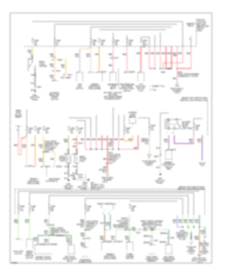
Power Distribution Wiring Diagram (1 of 3) for Ford Transit Connect 2012

List of elements for Power Distribution Wiring Diagram (1 of 3) for Ford Transit Connect 2012:
- (except taxi) left heated winshield relay
- (except taxi) right heated winshield relay
- (info not available)
- (left rear corner of engine compt) battery junction box (bjb)
- (taxi)
- (taxi) auxiliary blower motor assembly
- (tbj2010-tc wiring harness, near breakout to c268) s272
- 1 of 3)
- Abs test connector
- Anti-lock brake system (abs) module
- Auxiliary blower motor relay (taxi)
- Battery
- Block connector
- Blower motor relay
- C1035a
- C1035b
- C1045
- C126
- C175b
- C211
- C213
- C215
- C268
- Central junction box (cjb) (behind left side
- Central junction box (cjb) (behind left side of dash)
- Data link connector (dlc)
- Daytime running lamps relay
- Evap canister vent control solenoid
- Except taxi
- From fuse 3 (diagram 1 of 3)
- From splice s242 (diagram 2 of 3)
- From splice s244 (diagram 3 of 3)
- Fuel pump diode
- Fuel pump relay
- Fuse (taxi) 10a
- Fuse (taxi) 20a
- Fuse (up- fitter) 10a
- Fuse 10a
- Fuse 15a
- Fuse 20a
- Fuse 25a
- Fuse 30a
- Fuse 40a
- Fuse 50a
- Fuse 50a (or 20a)
- G104 (left side of engine compt)
- G105 (left side of engine)
- G200 (left kick panel)
- Generator
- High beam relay
- High speed fan control relay
- Ignition relay
- Inline fuse
- Left heated windshield relay
- Left turn relay
- Low beam interrupt relay
- Low speed fan control relay
- Midi fuse 200a
- Of dash)
- Pcm power relay
- Powertrain control module (pcm)
- Red
- Right heated winshield relay (except taxi)
- Right turn relay
- S118 (dash panel to headlamp junction wiring harness, in under bjb)
- S154
- S205
- S228
- S316
- Starter motor
- Starter relay
- Taxi
- Telematics module
- To block connector (diagram
- To ignition switch (diagram 3 of 3)
- To splice s242 (diagram 2 of 3)
- To splice s243 (diagram 2 of 3)
- To splice s273 (diagram 2 of 3)
- Upfitter
Power Distribution Wiring Diagram (2 of 3) for Ford Transit Connect 2012
List of elements for Power Distribution Wiring Diagram (2 of 3) for Ford Transit Connect 2012:
- (behind left side of dash) central junction box (cjb)
- (body wiring harness, near breakout to c219) s308
- (body wiring harness, near breakout to restraints control module) s305
- (main wiring harness, near breakout to instrument cluster) s235
- (main wiring harness, near breakout to microphone) s231
- (not used)
- 1 of 3)
- Battery junction box (bjb) (left rear corner of engine compt)
- Battery saver relay (upfitter)
- Brake pedal position switch
- C201a
- C201b
- C201c
- C201d
- C201e
- C213
- C219
- C220b
- C237
- C2409a
- C3293a
- C3293b
- C423
- C438
- C510
- C610
- Central
- Cluster (ic)
- Defrost relay
- Except taxi
- Exterior rear view mirror switch
- From fuse 19 (diagram 1 of 3)
- From fuse 9 (diagram
- From ignition relay (diagram 1 of 3)
- Front cigar lighter
- Front power point
- Front wiper relay
- Fuse (taxi) 15a
- Fuse 10a
- Fuse 15a
- Fuse 20a
- Fuse 25a
- Fuse 5a
- Fuse 7.5a
- G200 (left kick panel)
- G200 (taxi) (left kick panel)
- G411 (except taxi) (base of right "d" pillar)
- Generic electronic module (gem)
- Generic electronics module (gem)
- Instrument
- Interior lamps relay
- Junction box (cjb) (behind left side of dash)
- Left rear wiper motor assembly
- Main light switch
- Master window control switch
- Nca
- One touch down window relay
- Rear door unlock relay
- Rear power point
- Red
- Reversing lamps relay
- Right rear wiper motor assembly
- S206
- S228
- S242 (main wiring harness, in breakout to cjb)
- S243 (main wiring harness, in breakout to cjb)
- S273 (main wiring harness, in breakout red
- S315
- Taxi
- Taxi roof lamp switch (taxi)
- Tire pressure monitoring system (tpms) module
- To centeral junction box (cjb) (diagram 1 of 3)
- To cjb) c213
- To splice s202 (diagram 3 of 3)
- To splice s205 (diagram 1 of 3)
- Windshield wiper motor
- Wiper/ washer switch
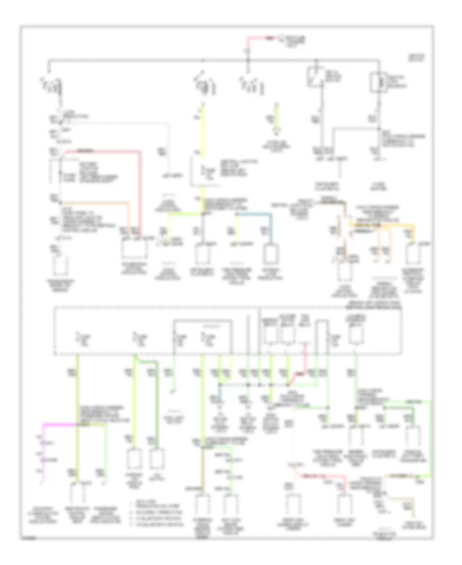
Power Distribution Wiring Diagram (3 of 3) for Ford Transit Connect 2012
List of elements for Power Distribution Wiring Diagram (3 of 3) for Ford Transit Connect 2012:
- (behind left side of dash) central junction box (cjb)
- (info not avaiblable)
- (late production)
- (main wiring harness, near breakout to antenna) s260
- (main wiring harness, near breakout to passenger air bag deactivation indicator) s219
- (main wiring harness, near breakout to speech recognition module)
- (tbj2010-tc wiring harness, near breakout to c268) s250
- 2012 early production
- 2012 late
- A/c switch
- Acc
- Accessory protocol interface module (apim) (w/ sync)
- Antenna (late production)
- Anti-lock brake system (abs) module
- Audio control module (acm)
- Battery junction box (bjb) (left rear corner of engine compt)
- Blower motor relay
- Box (cjb) (diagram 2 of 3)
- C110
- C126
- C175b
- C201a
- C211
- C213
- C220a
- C220b
- C2409a
- C240b
- C268
- C290a
- C290a c240b
- C310a
- C340b
- C438
- Central junction box (cjb) (behind left side of dash)
- Defrost relay
- Floor shifter
- Fog lamp relay
- From central junction l
- From fuse 7 (diagram 1 of 3)
- From ignition switch (diagram 3 of 3)
- Fuse 10a
- Fuse 7.5a
- Generic electronic module (gem)
- Ignition lock solenoid
- Ignition switch
- In breakout to cjb) s280
- Instrument cluster (ic)
- Key in ignition switch
- Low beam interrupt relay
- Main light switch
- Occupant classification system module (ocsm)
- Off
- Parking aid module (pam)
- Passenger air bag deactivation (pad) indicator
- Passive anti-theft transceiver
- Powertrain control module (pcm)
- Production or later
- Rear view camera
- Rear view camera display mirror
- Red
- Restraints control module (rcm)
- Run
- Run acc
- S202
- S237 (main wiring harness, in breakout to ignition switch)
- S244 (main wiring harness,in breakout to cjb)
- S281
- Start
- Start diode
- Steering angle sensor module (sasm)
- Telematics module
- Tire pressure monitoring system (tpms) module
- To ignition relay (diagram 1 of 3)
- To splice s118 (diagram 1 of 3)
- To splice s244 (diagram 3 of 3)
- Transmission range (tr) sensor
- Wiring harness, in breakout to powertrain control module)