POWER DISTRIBUTION
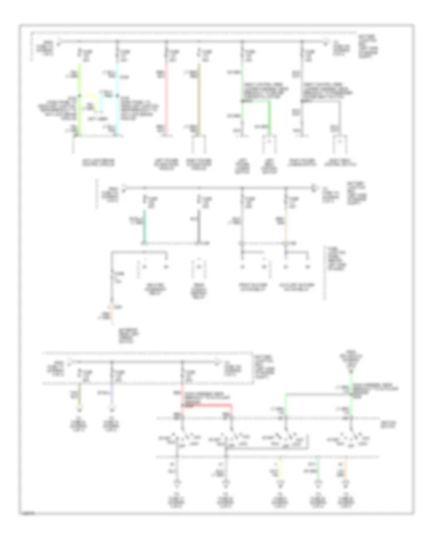
Power Distribution Wiring Diagram (1 of 4) for Ford Windstar 2000

List of elements for Power Distribution Wiring Diagram (1 of 4) for Ford Windstar 2000:
- (dash panel to headlamp harness, near breakout to left front wheel speed sensor) s123
- (dash panel to headlight junction, left rear of engine compt) s130
- (dash panel to headlight junction, near breakout to battery junction box) s127
- (starter motor relay & battery ground harness, near breakout for mass airflow sensor)
- (starter motor relay & battery ground harness, near breakout for mass airflow sensor) s142
- 2 of 4)
- A/c clutch relay
- Battery
- Battery junction box (left side of engine compt)
- C190
- C348
- Dual auxiliary relay box (at left rear side of engine compt)
- Electronic brake switch connector
- Engine cooling fan motor high speed relay
- Engine cooling fan motor low speed relay
- From fuse 105 (diagram 1 of 4)
- From fuse 6 (diagram 1 of 4)
- Front electronic module
- Fuel pump relay
- Fuse 10a
- Fuse 15a
- Fuse 25a
- Fuse 30a
- Fuse 50a
- Generator
- Horn relay
- Liftgate washer pump motor
- Liftgate wiper motor
- Liftgate wiper relay
- Pcm power relay
- Powertrain control module
- Red
- S124 (dash panel to headlamp harness, near breakout to left front wheel speed sensor)
- S126
- S141
- S143
- Starter interrupt relay
- Starter motor/ solenoid
- To fuse 102 (diagram 2 0f 4)
- To fuse 2 (diagram 1 of 4)
- To fuse 7 (diagram 1 of 4)
- To splice s226 (diagram
- Windshield washer pump motor
- Windshield wiper motor
- Windshield wiper on/ off relay
- Windshield wiper speed relay
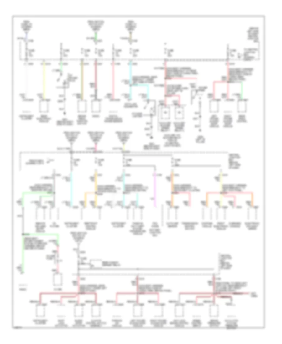
Power Distribution Wiring Diagram (2 of 4) for Ford Windstar 2000
List of elements for Power Distribution Wiring Diagram (2 of 4) for Ford Windstar 2000:
- (not used)
- (seat control feed jumper harness, near breakout to driver horizontal motor) s340
- (seat control feed jumper harness, near breakout to passenger power seat switch) s341
- Acc
- Anti-lock brake control module
- Auxiliary blower motor relay
- Battery junction box (left side of engine compt)
- C195
- C196
- C220
- Delayed accessory relay
- Exterior rear view mirror switch
- From fuse 104 (diagram 2 of 4)
- From fuse 112 (diagram 1 of 4)
- From fuse 117 (diagram 2 of 4)
- From splice s124 (diagram 1 of 4)
- Front blower motor relay
- Fuse 10a
- Fuse 20a
- Fuse 30a
- Fuse 40a
- Fuse 50a
- Fuse junction panel (behind left side of dash)
- Ignition switch
- Left power lumbar switch
- Left power sliding door module
- Left seat control switch
- Lock
- Lock off
- Nca
- Off
- Rear window defrost relay
- Red (main harness, near breakout to autolamp sensor) s225
- Red b1
- Red b3
- Right power lumbar switch
- Right power sliding door module
- Right seat control switch
- Run
- S128 (dash panel to headlamp junction, near breakout to anti-lock brake module)
- S129 (dash panel to headlamp junction, near breakout to anti-lock brake module)
- Sta
- Start
- To fuse 10 (diagram 3 of 4)
- To fuse 106 (diagram 2 of 4)
- To fuse 109 (diagram 4 of 4)
- To fuse 115 (diagram 2 of 4)
- To fuse 16 (diagram 3 of 4)
- To fuse 23 (diagram 3 of 4)
- To fuse 25 (diagram 3 of 4)
- To fuse 26 (diagram 3 of 4)
- To fuse 28 (diagram 3 of 4)
- To fuse 9 (diagram 3 of 4)
Power Distribution Wiring Diagram (3 of 4) for Ford Windstar 2000
List of elements for Power Distribution Wiring Diagram (3 of 4) for Ford Windstar 2000:
- (behind left side of dash) central junction box
- (main body harness, near breakout to left kick panel) s330
- (main harness, near breakout to air bag module) s209
- (main harness, near breakout to instrument cluster) s224
- (main harness, near breakout to message center) s207
- (main harness, near breakout to message center) s216
- (not used)
- (rear seat entertainment system interface harness, behind center of dash)
- A/c clutch cycling pressure switch
- Anti-lock brake control module
- Autolamp sensor
- Auxiliary a/c blower relay module (in central junction box)
- Auxiliary blower speed relay 1
- Auxiliary blower speed relay 2
- Battery junction box
- Blend door actuator
- Brake pedal position switch
- Brake pressure switch
- C116
- C126
- C195
- C196
- C200
- C201
- C202
- C211
- C219
- C231
- C239
- C240
- C244
- C260
- C343
- C346
- C352
- C355
- C445
- C907
- C915
- C917
- Cd player
- Central junction box (behind left side of dash)
- Climate control switch assembly
- Compass module
- Data link connector
- Digital transmission range sensor
- Electronic day/night mirror
- Filter
- From fuse 115 (diagram 2 of 4)
- From fuse 119 (diagram 2 of 4)
- From fuse 6, (diagram 3 of 4)
- From ignition switch a1 (diagram 2 of 4)
- From ignition switch a3 (diagram 2 of 4)
- From ignition switch a4 (diagram 2 of 4)
- From ignition switch i1 (diagram 2 of 4)
- From ignition switch sta (diagram 2 of 4)
- Front electronic module
- Fuse 10a
- Fuse 15a
- Fuse 20a
- G201 (behind right side of dash)
- G308 (left "b" pillar)
- I/p cigar lighter
- I/p power plug
- In-line fuse 1
- Instrument cluster
- Left power sliding door module
- Left side of dash) s218
- Nca
- Overhead console
- Parking aid module
- Passive anti-theft system transceiver module
- Pcm diode
- Power plug
- Radio
- Rear electronic module
- Rear radio control
- Rear window defrost relay
- Red
- Remote keyless entry module
- Restraint control module
- Right power sliding door module
- S202
- S208
- S301
- S350
- Shift lock actuator
- Speed control servo
- To central junction box (diagram 3 of 4)
- Transmission control switch
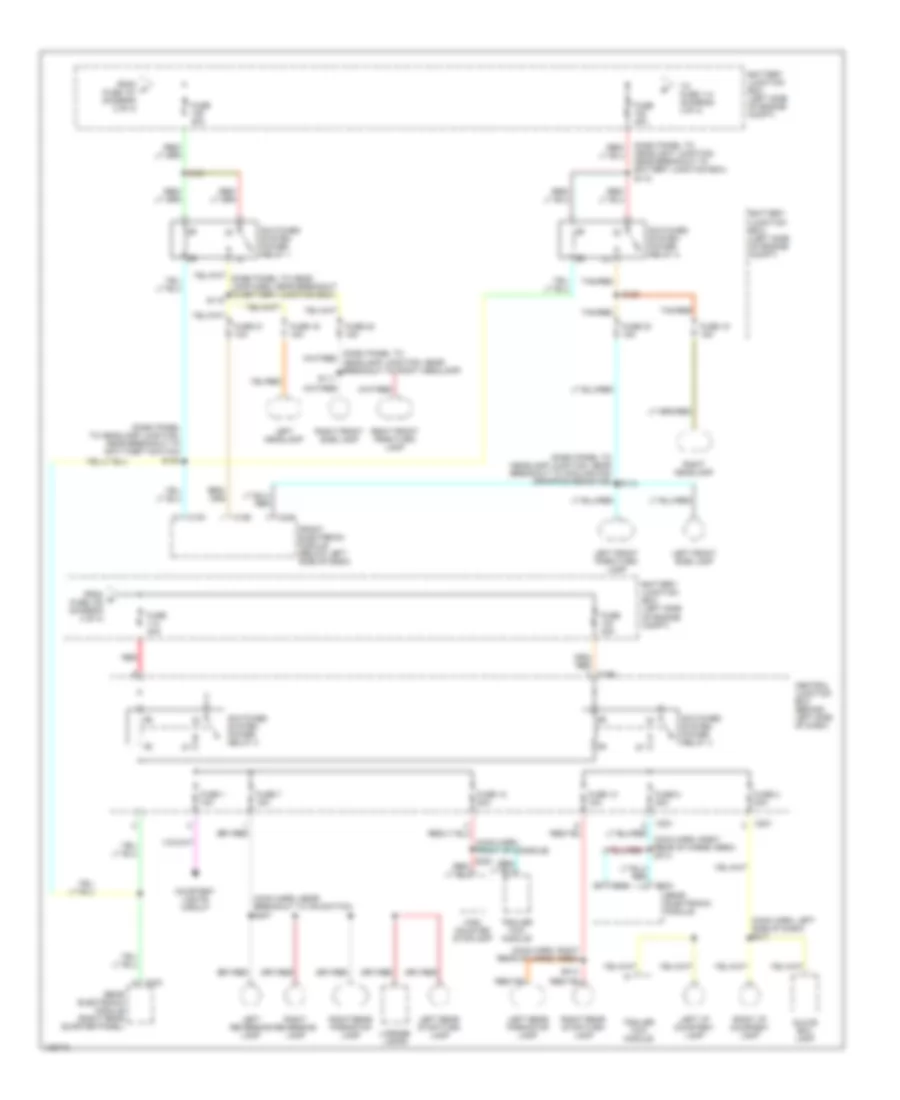
Power Distribution Wiring Diagram (4 of 4) for Ford Windstar 2000
List of elements for Power Distribution Wiring Diagram (4 of 4) for Ford Windstar 2000:
- (dash panel to headlamp junction, near breakout to anti-theft switch)
- (dash panel to headlamp junction, near breakout to cooling fan dropping resistor)
- (dash panel to headlight junction, near breakout to battery junction box) s118
- (main harn, front of console)
- (main harn, left side of dash) s217
- (main harn, near breakout to ifs switch) s307
- (main harn, right rear of cargo area)
- Battery junction box (left side of engine compt)
- C191
- C192
- C196
- C201
- C221
- C342
- C343
- C344
- C346
- Central junction box (behind left side of dash)
- Courtesy lights circuit
- From p fuse 121 (diagram 2 of 4)
- From q fuse 108 (diagram 4 of 4)
- Front electronic module (below left side of dash)
- Fuse 1 10a
- Fuse 12 20a
- Fuse 13 15a
- Fuse 15 15a
- Fuse 16 15a
- Fuse 2 20a
- Fuse 21 10a
- Fuse 22 15a
- Fuse 23 15a
- Fuse 40a
- Fuse 7 15a
- Fuse 8 20a
- Glove box lamp
- High mounted stoplamp
- Left front park/turn lamp
- Left front side lamp
- Left headlamp
- Left i/p courtesy lamp
- Left rear park/stop lamp
- Left rear stop/turn lamp
- Left reversing lamp
- License lamps
- Rear electronic module
- Rear electronic module (right rear quarter panel)
- Red
- Right front park/turn lamp
- Right front side lamp
- Right headlamp
- Right i/p courtesy lamp
- Right rear park/stop lamp
- Right rear stop/turn lamp
- Right reversing lamp
- S111
- S114
- S119
- S120
- S121
- S135
- S314
- Switched system power relay 1
- Switched system power relay 2
- Switched system power relay 3
- Switched system power relay 4
- Tan/red
- To fuse 114 (diagram 4 0f 4)
- Trailer tow module