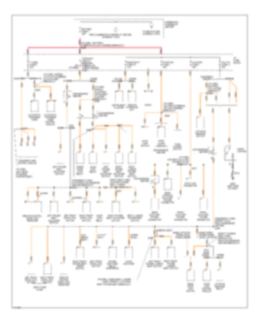
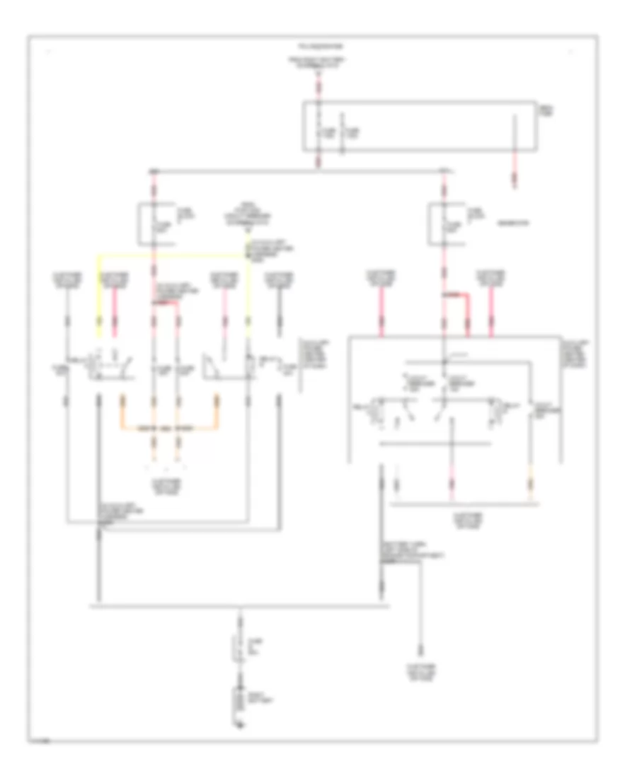
POWER DISTRIBUTION
Power Distribution Wiring Diagram (1 of 6) for GMC Yukon 1999

List of elements for Power Distribution Wiring Diagram (1 of 6) for GMC Yukon 1999:
- (auxiliary a/c harn, near blower motor relays)
- (crossbody harn, approx 22 cm from left door harness breakout)
- (diesel-eng harn, 6.5cm from ebcm breakout gasoline-eng harn, 12cm from ebcm breakout)
- (eng harn, approx 19cm from electronic brake control module breakout) s113
- (eng harn, near ebcm breakout)
- (i/p harn, near steering column harness breakout) s205
- (overhead console harn, between garage door opener & reading lamp)
- (stud a)
- (stud b)
- (vanity mirror jumper harn, approx 4 cm from inside rearview mirror)
- 175a
- 7.4l
- A nca
- A/c comp fuse 10a
- A/c compressor clutch relay
- Abs fuse 4 60a
- Aux fan fuse 30a
- Aux fuse 22 20a
- Aux pwr auto headlap fuse 22 20a
- Auxiliary cooling fan relay
- Auxiliary high blower motor relay
- Auxiliary low blower motor relay
- Auxiliary medium blower motor relay
- Auxiliary roof lamp relay
- Auxiliary roof lamp switch
- B red
- Blower fuse 3 50a
- Brake lamp relay
- C13
- Camp/trail fuse 30a
- Cargo lamp switch
- Convenience center
- Ctsy fuse 3 20a
- D13
- Daytime running lamps relay
- Diode
- Drl/fog fuse 15 20a
- Dual battery
- Ecm-b fuse 20a
- Electronic brake control module
- Evo/ passlock module
- Fog lamp relay
- Front dome lamp
- Front dome lamps
- Fuel pump oil pressure switch and sender
- Fuel pump relay
- Fusible link (10 ga-rust)
- Garage door opener
- Generator (base)
- Generator (uplevel)
- Headlamp & panel dimmer switch
- Headlamp and panel dimmer switch
- Headlamp control module
- Heater and a/c control switch
- Heater mirror relay
- High blower motor relay
- Horn fuse 20a
- Horn relay
- Htd mir fuse 10a
- I/p compartment box lamp
- I/p fuse block
- Instrument cluster (police package)
- Interior lamp control module
- Left battery (diesel)
- Left courtesy lamp
- Left front door courtesy lamp
- Left rear door courtesy lamp
- Left vanity mirror
- Lighting fuse 8 50a
- Mega fuse block
- Overhead console reading lamps
- Pickup only
- Pk lps fuse 9 20a
- Power outside rearview mirror switch
- Powertrain control module (diesel)
- Radio
- Radio batt fuse 19 10a
- Rear dome lamps
- Red
- Remote battery stud
- Right battery
- Right courtesy lamp
- Right front door courtesy lamp
- Right rear door courtesy lamp
- Right vanity mirror
- Rr defog fuse 30a
- S101
- S110
- S242 (i/p harn, 12cm from inflatable restraint switch breakout)
- S248 (crossbody harn, approx 35 cm from left front door harn breakout)
- S278
- S312 s312
- S401
- S426
- S443
- Security/ strg fuse 21 20a
- Seo fuse 30a
- Single battery (base)
- Single battery (uplevel)
- Spare power source
- Spotlamp (police package)
- Starter motor solenoid
- Stop fuse 2 50a
- Suburban/ utility
- To fusible link (diagram 5 of 6)
- To megafuse (diagram 6 of 6)
- To underhood fuse-relay center (diagram 2 of 6)
- Underhood fuse- relay center
- Underhood fuse-relay center
- Underhood lamp
- Upper level
- Vehicle control module (gasoline)
- W/o rke
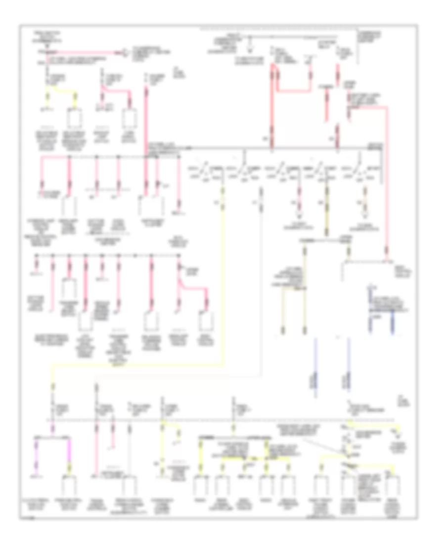
Power Distribution Wiring Diagram (2 of 6) for GMC Yukon 1999
List of elements for Power Distribution Wiring Diagram (2 of 6) for GMC Yukon 1999:
- (2dr w/ rke & 4dr)
- (crossbody harn, 20 cm from convenience center breakout) s255
- (crossbody harn, approx 19 cm from conenience center)
- (front-to-rear body harn, approx 6 cm from convenience center breakout)
- (i/p harn, 12cm from steering column harness breakout) s200
- (i/p harn, 4cm from auxiliary power outlet breakout)
- (i/p harn, 4cm from steering column harness breakout)
- (i/p harn, approx 10 cm into steering column harn breakout)
- (i/p harn, left rear of engine compartment)
- (power lumbar seat jumper harn, approx 13 cm from right power seat breakout)
- (upper level)
- (utility only)
- 30a (others)
- 8cm from i/p cluster breakout) s264
- Audio alarm module
- Audio amplifier
- Automatic
- Automatic transfer case
- Automatic transfer case control module
- Aux/pwr fuse 7 25a
- Base
- Base cargo door
- Base cargo doors/upper level liftgate
- Base liftgate/ upper level cargo doors
- Battery fuse 7 50a
- Cargo door lock relay
- Cig ltr fuse 13 20a
- Cigar lighter
- Convenience center
- D14
- D15
- Data link connector
- Door lock control module
- Door lock relay
- Electric
- From underhood fuse-relay center (diagram 1 of 6)
- Front auxiliary power connector
- G202 (left side of dash)
- I/p fuse block
- Instrument cluster
- Left front door lock switch
- Left front power lumbar seat switch
- Left power seat adjuster switch
- Liftgate release relay
- Liftgate release switch
- Non- base
- Others
- Pickup
- Police package
- Power amplifier relay (suburban)
- Pwr-accy circuit breaker (regular 20a cab/extended cab)
- Radio
- Radio batt fuse 19 10a
- Rear auxiliary power connector
- Rear console auxiliary power connector
- Rear door lock switch
- Red
- Remote control door lock receiver
- Right front door lock switch
- Right front power lumbar seat switch
- Right front power seat umbar switch
- Right lumbar power seat switch
- Right power seat adjuster switch
- S212
- S218
- S236
- S237
- S255
- S256
- S272
- S299
- S300
- S434
- Stop lamp switch
- Stop/haz fuse 1 20a
- Suburban/ utility
- T case fuse 2 20a
- To seats fuse (diagram 3 of 6)
- Transfer case control module
- Turn/ hazard switch
- Underhood fuse-relay center
- Upper level
- Upper levle
- Vehicle interface unit
- W/ rke
- W/bench seat
- W/o rke
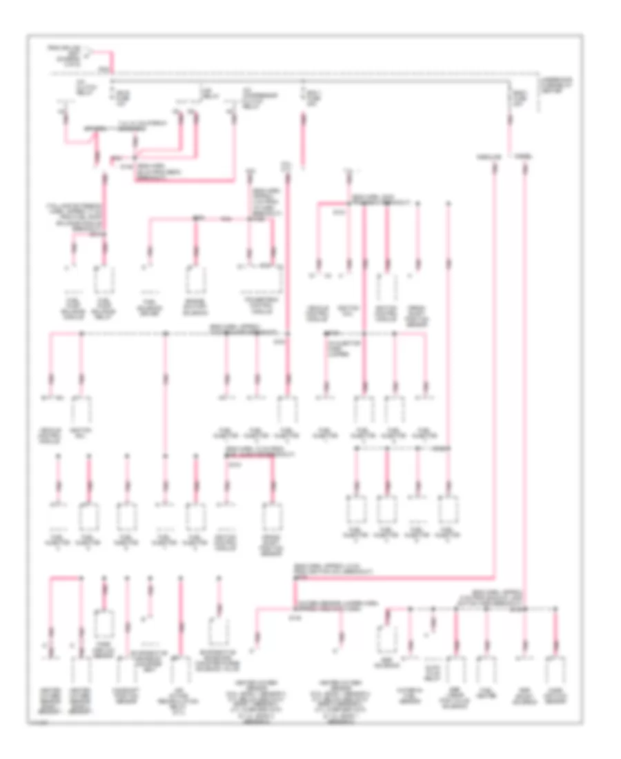
Power Distribution Wiring Diagram (3 of 6) for GMC Yukon 1999
List of elements for Power Distribution Wiring Diagram (3 of 6) for GMC Yukon 1999:
- (a/t)
- (battery harn, red
- (floor console harn, 33 cm heated seat switch breakout)
- (gas) (diesel)
- (i/p harn, 12cm from steering column harn breakout) pnk
- (i/p harn, 22 cm before radio harn breakout) s292
- (i/p harn, 4 cm from steering column harn breakout) s213
- (i/p harn, 8 cm from automatic transfer case module breakout)
- (i/p harn, approx 8 cm from steering column harn breakout) s201
- (inside left front door harn at breakout to window motor regulator)
- (m/t)
- (w/o rke) (w/ rke)
- A j
- A/t
- Acc
- Air bag fuse 10 10a
- At left side of eng compt) s167
- Audio alarm module
- Backup lamp switch
- Body control module
- C210
- Clutch pedal position switch
- Convenience center
- Crank fuse 8 10a
- Cross body harn, 8cm from convenience center breakout)
- Daytime running lamps module
- Daytime running lamps relay
- Drl/radio override (police package)
- Electrochromic rearview mirror w/ compass
- Evo/ passlock module
- From ignition switch (diagram 3 of 6)
- From underhood o
- Fuse-relay center (diagram 2 0f 6)
- Gauges fuse 4 10a
- Headlamp control module
- Headlamp/ panel dimmer switch
- I/p fuse block
- Ign a fuse 6 40a 50a
- Ign b fuse 5 50a
- Ignition switch
- Inflatable restraint i/p module switch (pickup)
- Inflatable restraint sensing and diagnostic module
- Instrument cluster
- Interior lamp control module or remote control door lock receiver
- Lock
- Low coolant level indicator module (diesel)
- M/t
- Off
- Others
- Park/neutral position switch
- Pnk
- Pnk k
- Pnk s207
- Power window master switch
- Pwr wdo circuit breaker 30a
- Radio
- Radio fuse 17 10a
- Rear stereo controller
- Rear window lockout switch (4-dr)
- Rear window wiper/washer switch (suburban/utility)
- Red
- Right front power window switch (2 dr & utility)
- Rr wiper fuse 23 25a
- Run
- S266
- S290
- S501
- Start
- Starter relay
- To s206 (diagram 5 of 6)
- To s207 (diagram 3 of 6)
- To s285 (diagram 6 of 6)
- To seats fuse (diagram 5 of 6)
- To underhood fuse-relay center (diagram 4 of 6)
- Trans fuse 20 10a
- Trans- mission controls
- Transfer case control module (selectable 4wd electric shift)
- Transfer case select switch
- Turn b/u fuse 16 20a
- Turn signal switch
- Underhood fuse-relay center
- Upper level
- Vehicle interface unit
- Vehicle speed sensor buffer (diesel)
- Windshield wiper motor module
- Windshield wiper/ washer switch
- Wiper fuse 11 25a
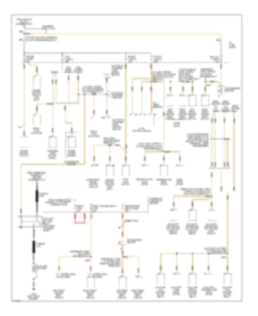
Power Distribution Wiring Diagram (4 of 6) for GMC Yukon 1999
List of elements for Power Distribution Wiring Diagram (4 of 6) for GMC Yukon 1999:
- (eng harn, 12 cm from fuel injector breakout)
- (eng harn, 30cm from ebcm breakout)
- (eng harn, approx 12 cm from ignition coil breakout)
- (eng harn, approx 4 cm from i/p harn breakout) s166
- (eng harn, approx 5 cm from backup lamp switch harn breakout)
- (eng harn, approx 8 cm from egr breakout)
- (eng harn, s146
- (in injector harn jumper)
- (oxygen sensor jumper harn, approx 19cm into harn)
- (taillamp extension harn, approx 17 cm from fuel pump
- 26 cm from ebcm breakout)
- 5.0l, 5.7l
- 6.5l pnk
- 7.4l
- 7.4l w/ california emissions
- A/c clutch relay
- A/c compressor clutch relay
- Air intake recirculation relay (5.7l)
- Air relay
- Balance module breakout) s315
- C11
- C12
- Camshaft position sensor
- Crank- shaft position sensor
- Diesel
- Ecm 1 fuse 20a
- Egr boost solenoid
- Egr linear pwm valve solenoid
- Egr solenoid
- Eng-1 fuse 20a
- Engine shutoff solenoid
- Evaporative emission canister vent
- Evaporative emissions canister purge solenoid valve
- From splice s207 k (diagram 3 of 6)
- Fuel heater
- Fuel injector
- Fuel pump balance module
- Fuel pump balance relay
- Fuel solenoid driver
- Gasoline
- Glow plug relay
- Heated oxygen sensor (5.ol: bank 1 sensor 2, 5.7l below 8600 gvw: bank 2 sensor 2, 5.7l over 8600 gvw & 7.4l: bank 1 sensor 2)
- Heated oxygen sensor (5.ol: bank 1 sensor 3, 5.7l below 8600 gvw: bank 1 sensor 2, 5.7l over 8600 gvw & 7.4l: bank 2 sensor 2)
- Heated oxygen sensor bank 1 sensor 1
- Heated oxygen sensor bank 2 sensor 1
- Ign e fuse 10a
- Ignition coil
- Ignition control module
- Mass air flow sensor
- Mass airflow sensor
- Others
- Pnk
- Powertrain control module
- S104
- S108
- S148
- S154
- S155
- S161
- S190
- Underhood fuse-relay center
- Vehicle control module
- Water-in- fuel sensor
Power Distribution Wiring Diagram (5 of 6) for GMC Yukon 1999
List of elements for Power Distribution Wiring Diagram (5 of 6) for GMC Yukon 1999:
- (auxiliary a/c harn, 17cm from blower motor relays)
- (crossbody harn, 27 cm from left rear heated seat breakout)
- (crossbody harn, approx 25 cm from sdm breakout)
- (eng harn, 7cm from ebcm) breakout)
- (floor console harn, approx 28 cm from left heated switch breakout) s332
- (hvac harn, approx 4 cm from recirculation door breakout)
- (i/p harn, 6cm from steering column harness breakout)
- (i/p harn, approx 7cm from inflatable restraint switch breakout) s268
- (i/p harn, approx 8 cm from steering column breakout)
- (others)
- (rear hvac control harn, approx 5 cm from hvac logic module breakout) s308
- (tailamp extension harn, appr0x 10 cm from breakout to ground at left side frame rail, near crossmember)
- (upper level)
- 4wd fuse 24 25a
- A13
- Automatic transfer case control module
- Automatic transfer case only
- Automatic transfer case select switch
- Auxiliary battery
- Auxiliary battery relay (left rear of engine compt)
- Auxiliary heater and a/c control logic module
- Auxiliary heater and a/c control module (front)
- Auxiliary heater and a/c control module (rear)
- Auxiliary high blower motor relay
- Auxiliary low blower motor relay
- Auxiliary medium blower motor relay
- Auxiliary mode door motor
- Auxiliary temperature door motor
- Brake fuse 18 10a
- Convenience center
- Crossbody harn, 20 cm from sdm breakout)
- Cruise control module (gas only)
- Cruise control switch
- Cruise fuse 6 10a
- Diesel
- E10
- Electronic brake control module
- From ignition switch (diagram 3 of 6)
- From underhood e fuse-relay center (diagram 3 of 6)
- From underhood fuse-relay center (diagram 1 of 6)
- Front axle actuator
- Front heated seats fuse 20a
- Fusible link
- G100 (left front fender)
- Gas, base models
- Gas, others models
- Htr-a/c fuse 12 25a
- Hvac control module
- I/p fuse block
- Left front heated seat module
- Left front heated seat switch
- Left rear heated seat module
- Left rear heated seat switch
- Mode door motor
- Rear heated seats fuse 20a
- Rear heater only
- Rear heater w/ cargo doors
- Rear heater w/ lift- gate
- Recirculation door motor
- Red
- Right front heated seat module
- Right front heated seat switch
- Right rear heated seat module
- Right rear heated seat switch
- Rr hvac fuse 5 10a
- S151
- S206
- S233
- S235
- S238
- S243
- S281
- S324
- S326
- S400
- Seats fuse 40a
- Spare power source
- Stop lamp switch
- Suburban utility only
- Temperature door motor
- Transfer case switch (k3500)
- Underhood fuse-relay center
- Upper level
- Vehicle control module (gas only)
- W/ rear defrost
Power Distribution Wiring Diagram (6 of 6) for GMC Yukon 1999
List of elements for Power Distribution Wiring Diagram (6 of 6) for GMC Yukon 1999:
- (battery harn, left side of engine compartment) s167
- (in auxiliary power center harness) s285
- (in auxiliary power center harness) s286
- (in auxiliary power center harness) s287
- 30a
- 6j1
- Auxiliary power center (center of dash)
- Cicuit breaker 15a
- Cicuit breaker 25a
- Customer installed options
- From pwr wdo circuit breaker (diagram 3 of 6)
- From right battery (diagram 1 of 6)
- Fuse
- Fuse 175a
- Fuse 60a
- Fuse b 60a
- Fuse block
- Generator
- Mega fuse
- Pnk
- Police package
- Red
- Relay a
- Relay b
- Right battery
- S168
- S288
- S289
- Z56