POWER DISTRIBUTION
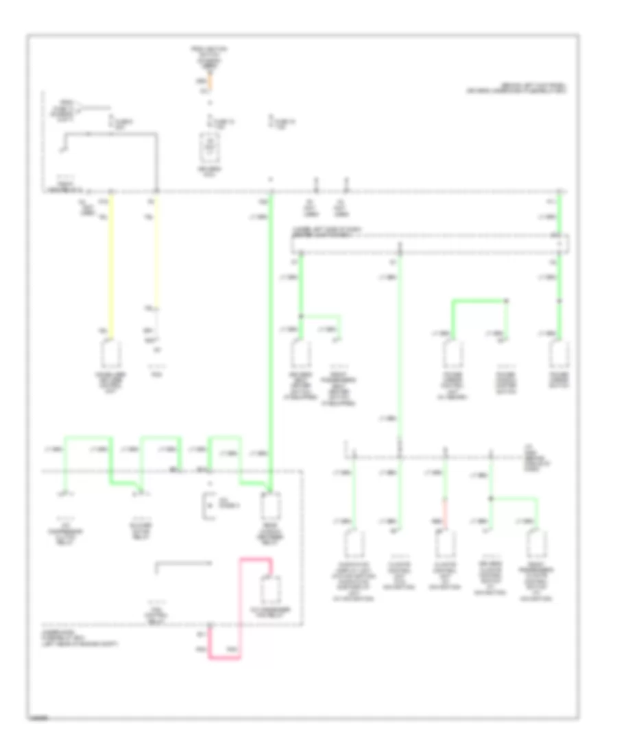
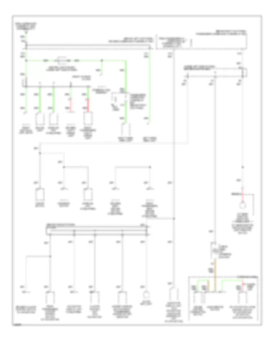
Power Distribution Wiring Diagram (1 of 7) for Honda Accord Crosstour EX 2010

List of elements for Power Distribution Wiring Diagram (1 of 7) for Honda Accord Crosstour EX 2010:
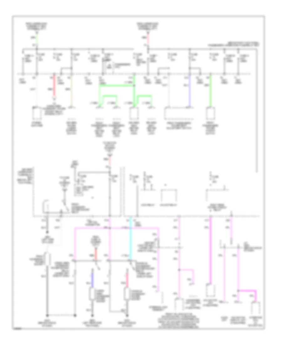
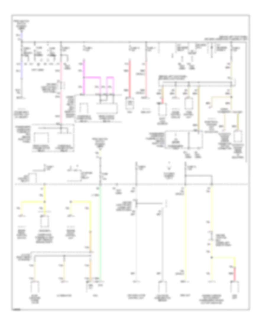
Power Distribution Wiring Diagram (2 of 7) for Honda Accord Crosstour EX 2010
List of elements for Power Distribution Wiring Diagram (2 of 7) for Honda Accord Crosstour EX 2010:
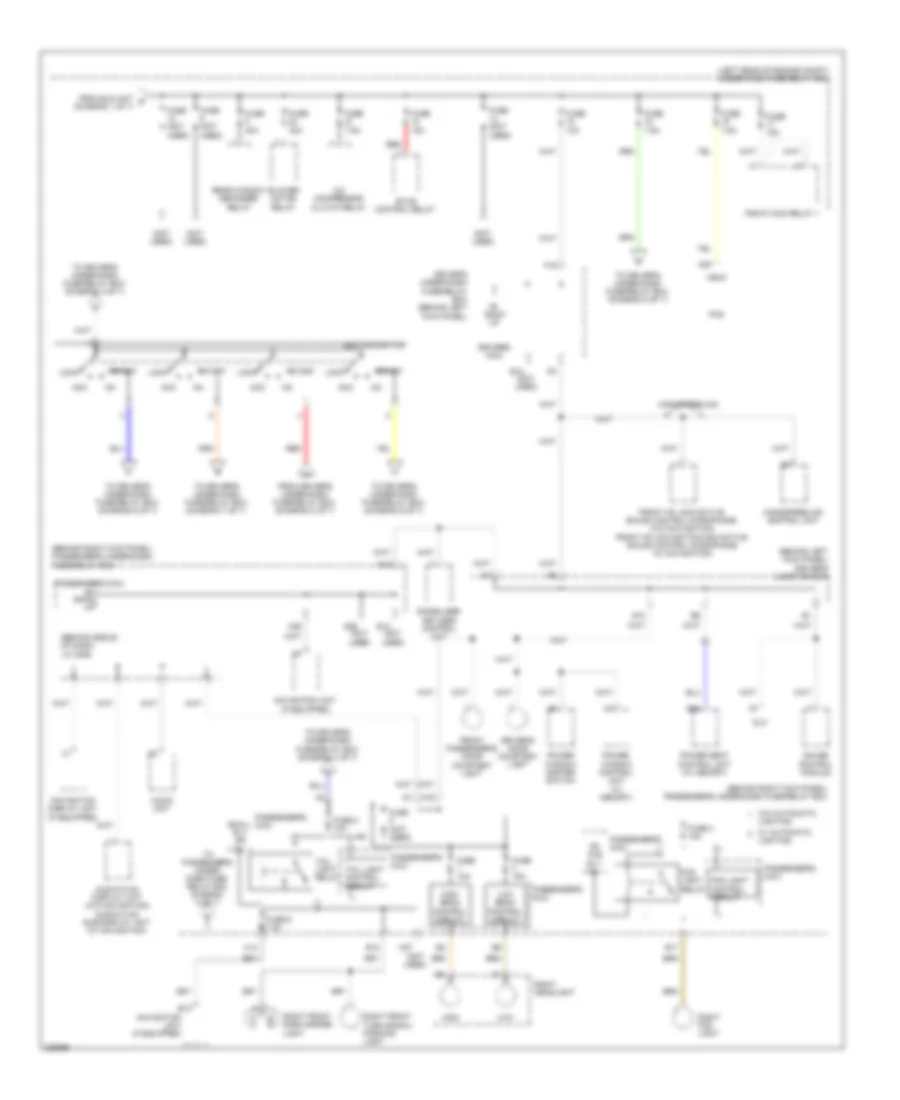
Power Distribution Wiring Diagram (3 of 7) for Honda Accord Crosstour EX 2010
List of elements for Power Distribution Wiring Diagram (3 of 7) for Honda Accord Crosstour EX 2010:
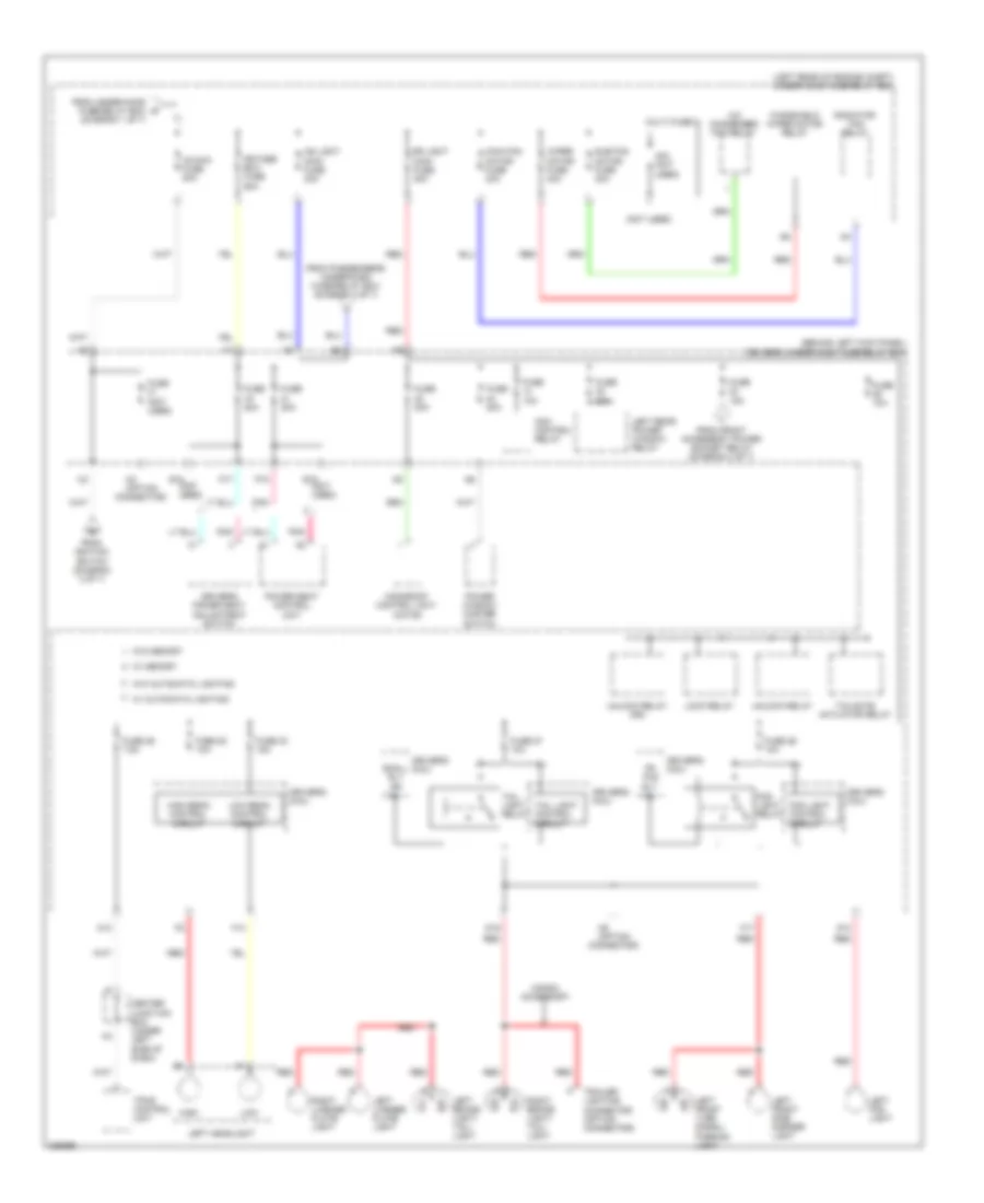
Power Distribution Wiring Diagram (4 of 7) for Honda Accord Crosstour EX 2010
List of elements for Power Distribution Wiring Diagram (4 of 7) for Honda Accord Crosstour EX 2010:
Power Distribution Wiring Diagram (5 of 7) for Honda Accord Crosstour EX 2010
List of elements for Power Distribution Wiring Diagram (5 of 7) for Honda Accord Crosstour EX 2010:
Power Distribution Wiring Diagram (6 of 7) for Honda Accord Crosstour EX 2010
List of elements for Power Distribution Wiring Diagram (6 of 7) for Honda Accord Crosstour EX 2010:
Power Distribution Wiring Diagram (7 of 7) for Honda Accord Crosstour EX 2010
List of elements for Power Distribution Wiring Diagram (7 of 7) for Honda Accord Crosstour EX 2010: