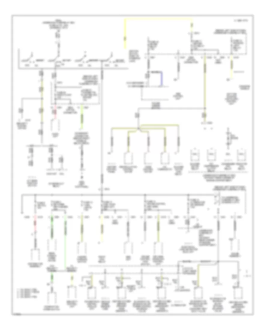
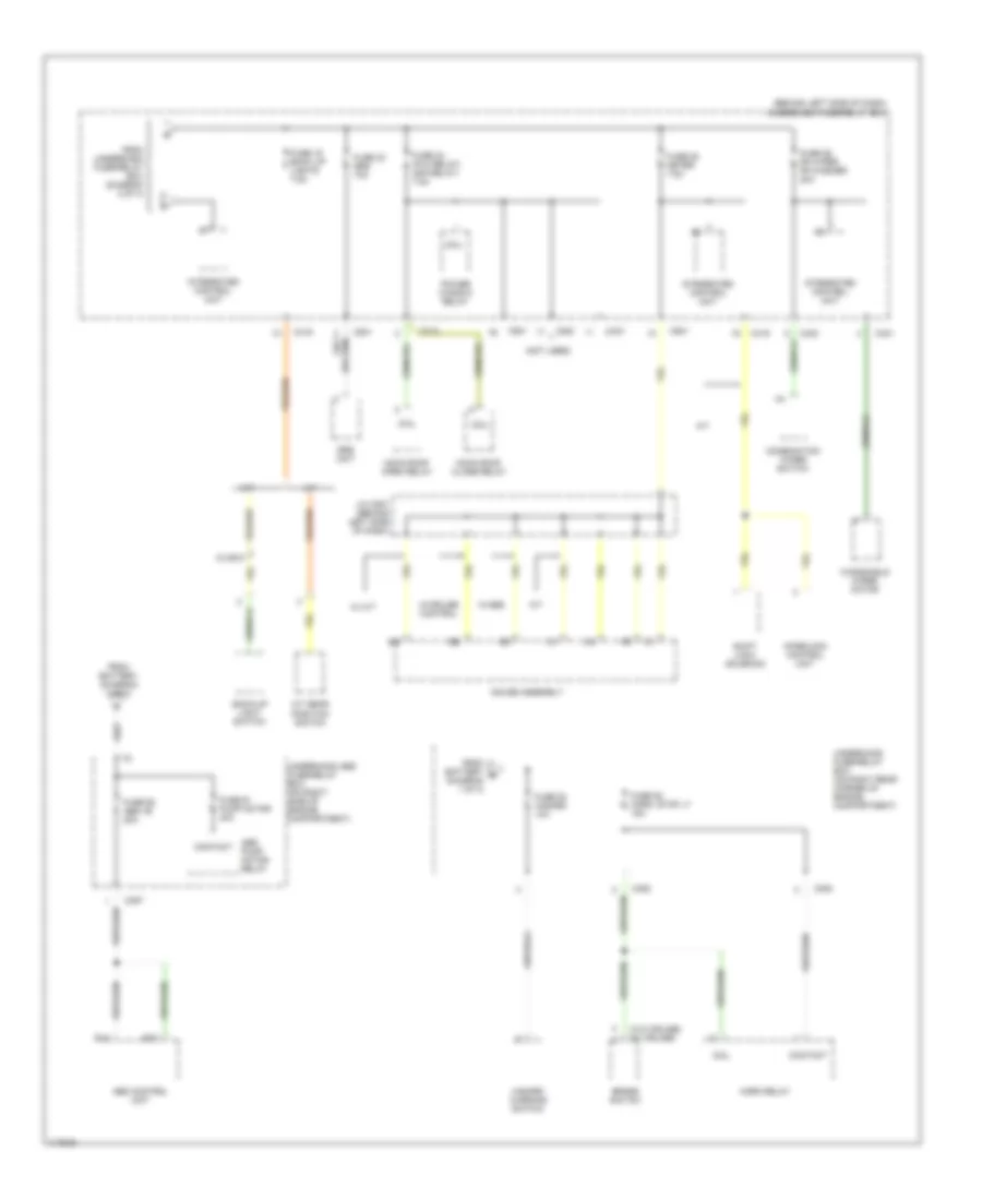
POWER DISTRIBUTION
Power Distribution Wiring Diagram (1 of 3) for Honda Civic DX 1999

List of elements for Power Distribution Wiring Diagram (1 of 3) for Honda Civic DX 1999:
- (ex vtec-e w/ m/t)
- (on right rear corner of engine compartment) underhood fuse/relay box
- (sedan) 1
- (vtec-e w/ m/t)
- A/c compressor clutch relay
- A/t
- Alternator
- Audio unit
- B10
- B21
- Battery
- Blower motor relay
- C 1995 vftc
- C10
- C351
- C352
- C419
- C420
- C422
- C551
- C712
- C926 (option connector)
- Canadian models
- Ceiling light
- Combination light switch
- Condenser fan relay
- Contact
- Data link connector (dlc) (partial)
- Daytime running lights (drl) control unit
- Electrical load detector (eld) unit
- From underhood fuse/relay box (fuse 48 headlight, 30a) (diagram 1 of 3)
- Fuse 1 (not used)
- Fuse 2 (not used)
- Fuse 20 running light 7.5a
- Fuse 33 interlock unit 7.5a
- Fuse 41 battery 80a
- Fuse 42 ig1 40a
- Fuse 43 interior light 7.5a
- Fuse 44 fi e/m 15a
- Fuse 46 power window 40a
- Fuse 47 back up 7.5a
- Fuse 48 headlight 30a
- Fuse 50 rear defogger 30a
- Fuse 51 door lock unit, roof 20a
- Fuse 54 option 40a
- Fuse 55 heater motor 40a
- Fuse 56 condenser fan 20a
- Fuse 57 cooling fan 20a
- Fuse 6 3a
- Heater control panel
- Integrated control unit
- Keyless door lock control unit
- Moon roof close relay
- Moon roof open relay
- Not used
- Pgm-fi main relay
- Power door lock control unit
- Power window relay
- Powertrain control module (pcm) or engine control module (ecm)
- Radiator fan relay
- Rear window defogger relay
- Security control unit connector (option)
- Security system connector (option)
- Spot lights
- Starter
- Starter solenoid
- Steering lock
- T101
- T102
- To ignition switch (diagram 2 of 3)
- To underhood abs fuse/relay box (diagram 3 of 3)
- To underhood fuse/relay box (fuse 53 hazard, 10a) (diagram 3 of 3)
- To underhood fuse/relay box (fuse 55 heater motor, 40a) (diagram 1 of 3)
- Trunk light
- Underdash fuse/relay box (behind left side of dash)
- Underdash fuse/relay box (behind left side of dash)
- Underhood fuse/relay box (on right rear corner of engine compartment)
- Us models: lx, ex, hx, dx-v, & si canadian models: ex & si
- W/ keyless entry
- W/o keyless entry
Power Distribution Wiring Diagram (2 of 3) for Honda Civic DX 1999
List of elements for Power Distribution Wiring Diagram (2 of 3) for Honda Civic DX 1999:
- (behind left side of dash) underdash fuse/relay box
- (canada)
- (not used)
- (us)
- (w/ defogger)
- (w/o defogger)
- 1.6l dohc vtec 1.6l sohc vtec-e
- 1.6l sohc 1.6l sohc vtec
- A/c compressor clutch relay
- A/c diode
- A/c thermostat
- A/t
- A/t gear position switch
- Abs control unit
- Acc
- Accessory connector (behind front console, below radio)
- Alternator
- Audio unit
- B15
- Blower motor high relay
- Blower motor relay
- C 1995 vftc
- C352
- C416
- C419
- C420
- C421
- C423
- C439
- C501
- C551
- C801
- C913
- C928 (option connector)
- C929 (option connector)
- Canadian models
- Coil
- Combination wiper switch
- Condenser fan relay
- Contact
- Cruise control main switch
- Daytime running lights (drl) control unit
- Distributor assembly
- Electrical load detector (eld) unit
- Evaporative emission (evap) bypass solenoid valve
- Evaporative emission (evap) control canister vent shut valve
- Evaporative emission (evap) purge control solenoid valve
- Except vtec-e m/t
- From underhood fuse/relay box (fuse 42 ig1, 40a) (diagram 1 of 3)
- Fuse 12 turn lights 7.5a
- Fuse 13 fuel pump (srs unit) 15a
- Fuse 14 cruise control (keyless) 7.5a
- Fuse 15 alternator (sp sensor) 7.5a
- Fuse 16 rr def relay 7.5a
- Fuse 17 heater a/c relay 7.5a
- Fuse 18 (running light relay) 7.5a
- Fuse 27 cigarette lighter acc socket 10a
- Fuse 28 radio clock 10a
- Fuse 3 rr wiper (rr washer) 10a
- Fuse 9 ign coil 15a
- G200 (left kick panel)
- Gauge assembly
- Hazard warning switch
- Heated oxygen sensor (primary h02s) (sensor 1)
- Heated oxygen sensor (secondary h02s) (sensor 2)
- Heater control panel
- Ignition switch (part of steering lock)
- J/c c115 (left rear of engine)
- Keyless doorlock control unit
- Lock
- M/t
- Mode control motor
- Pgm-fi main relay
- Power mirror switch
- Powertrain control module (a/t)
- Radiator fan relay
- Rear window wiper motor
- Recirculation control motor
- Red
- Security control unit
- Security system option
- Srs unit
- Start
- Starter cut relay
- To underdash fuse/relay box (diagram 3 of 3)
- Underhood fuse/relay box (on right rear corner of engine compartment)
- Us models
- Vehicle speed sensor (vss)
- W/ security system
- W/o security system
Power Distribution Wiring Diagram (3 of 3) for Honda Civic DX 1999
List of elements for Power Distribution Wiring Diagram (3 of 3) for Honda Civic DX 1999:
- (behind left side of dash) underdash fuse/relay box
- (not used)
- (w/o cruise) (w/ cruise)
- 15 or 6
- A/t
- A/t gear position switch
- Abs control unit
- Abs pump motor relay
- B14
- B15
- Back-up light switch
- Brake switch
- C352
- C353
- C357
- C419
- C420
- C421
- C423
- C501
- C712
- C801
- Coil
- Combination wiper switch
- Contact
- From battery (diagram 1 of 3)
- From battery b (diagram 1 of 3)
- From underdash fuse/relay box (diagram 2 of 3)
- Fuse 19 back up lights 7.5a
- Fuse 23 srs 10a
- Fuse 24 (p/w relay) (s/r relay) 7.5a
- Fuse 25 meter 7.5a
- Fuse 26 fr wiper fr washer 20a
- Fuse 52 horn, stop lt 15a
- Fuse 53 hazard 10a
- Fuse 61 pump motor 40a
- Fuse 62 abs +b 20a
- Gauge assembly
- Hazard warning switch
- Horn relay
- Integrated control unit
- Interlock control unit
- J/c c507 (behind left side of dash)
- M/t
- Moon roof close relay
- Moon roof open relay
- Power window relay
- Shift lock solenoid
- Srs unit
- Underhood abs fuse/relay box (on right side of engine compartment)
- Underhood fuse/relay box (on right rear corner of engine compartment)
- W/ m/t
- W/abs
- W/cruise control
- Windshield wiper motor