POWER DISTRIBUTION
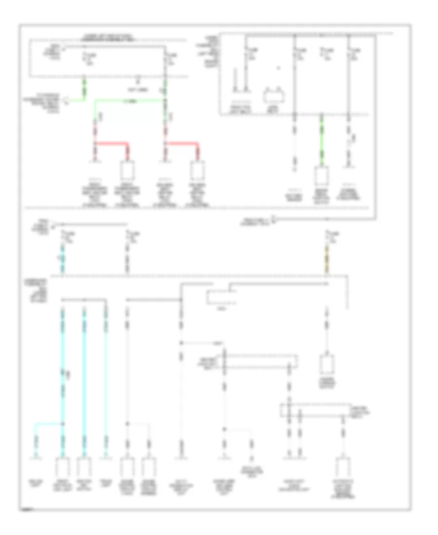
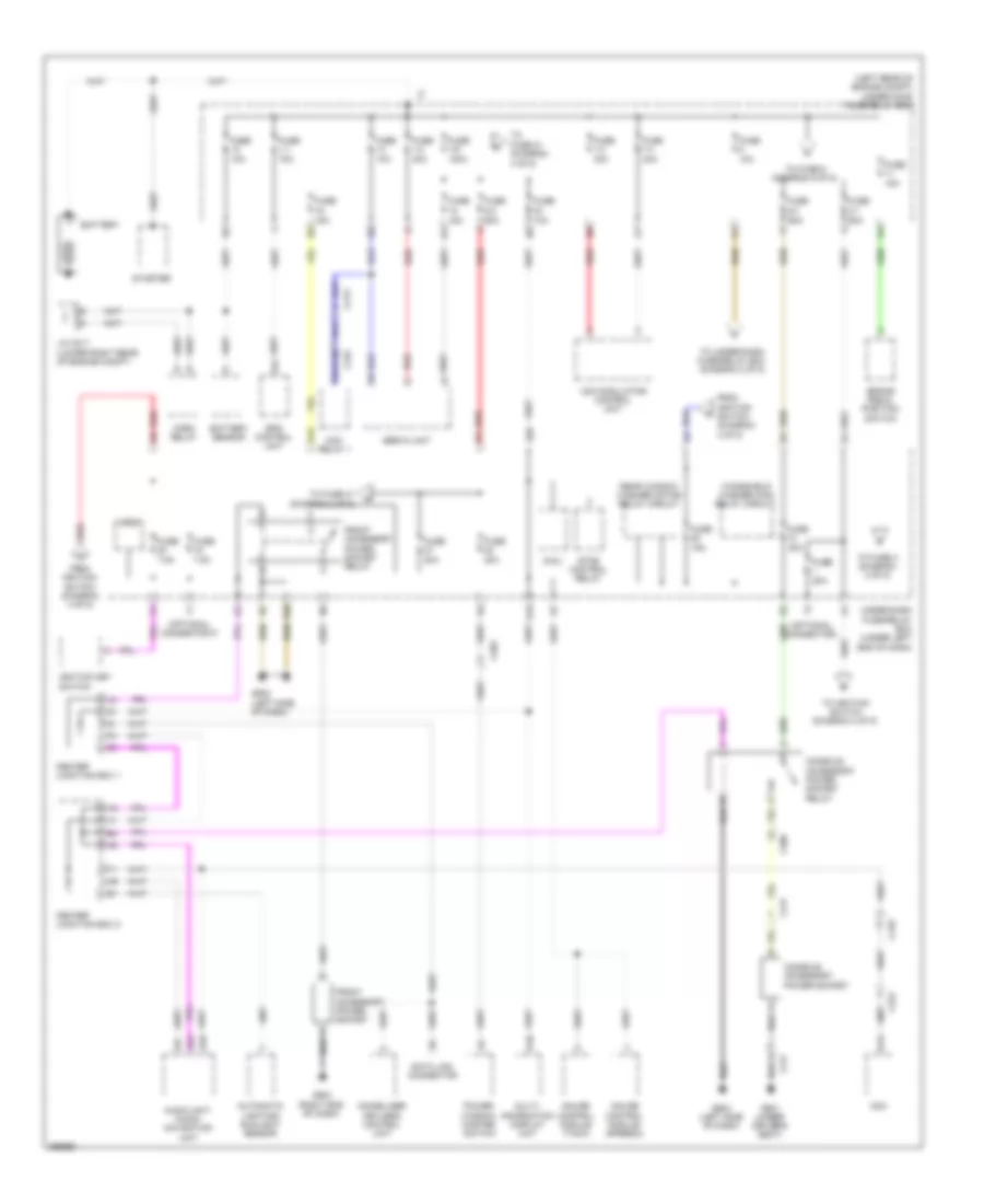
Power Distribution Wiring Diagram, Except Hybrid (1 of 5) for Honda Civic Si 2013

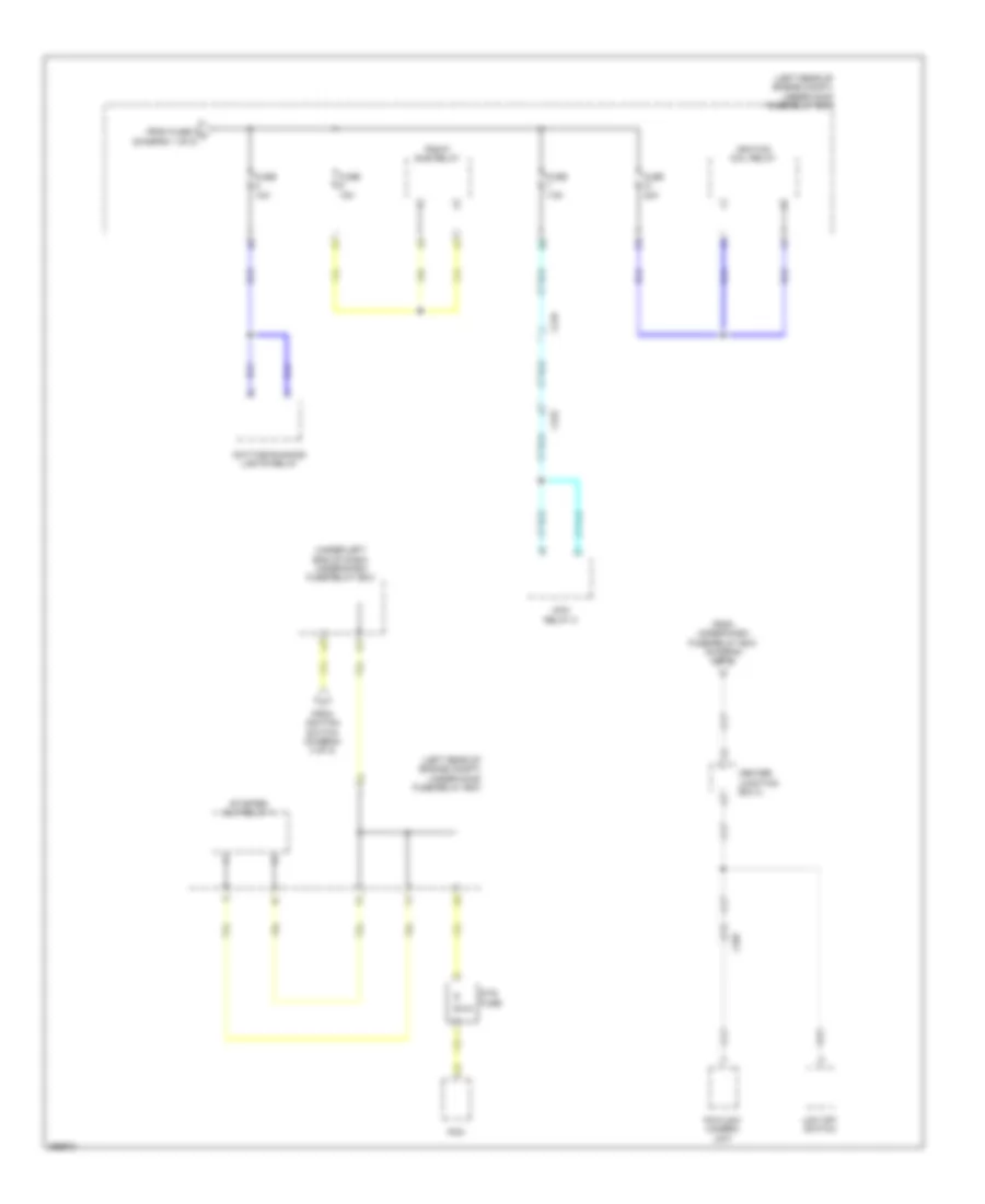
List of elements for Power Distribution Wiring Diagram, Except Hybrid (1 of 5) for Honda Civic Si 2013:
- (left rear of engine compt) under-hood fuse/relay box
- (not used)
- (sedan) (coupe)
- A/c compressor clutch relay
- A/c condenser fan relay
- Alternator
- Battery
- Blower motor relay
- C203
- C206
- D/l dr unlock relay
- D/l lock relay
- D/l unlock relay
- D12
- Eld unit
- Eps control unit
- Etcs control relay
- Fuse 1-1 70a
- Fuse 1-3 30a
- Fuse 1-4 30a
- Fuse 1-6 100a
- Fuse 10a
- Fuse 15a
- Fuse 2-1 50a
- Fuse 2-10 20a
- Fuse 2-11 20a
- Fuse 2-2 60a
- Fuse 2-3 60a
- Fuse 2-4 30a
- Fuse 2-6 30a 40a
- Fuse 2-8 40a
- Fuse 20a
- Fuse 7.5a
- Headlight low beam relay
- Ignition coil relay
- Micu
- Moonroof/ sunroof control unit/motor (if equipped)
- Pgm-fi main relay 1
- Pgm-fi sub-relay
- Power window master switch
- Power window relay
- Radiator fan relay
- Rear window defogger relay
- Red
- Starter
- T101
- Taillight relay
- To front accessory power socket relay (diagram 5 of 5)
- To fuse 12 (diagram 2 of 5)
- To fuse 14 (diagram 2 of 5)
- To fuse 28 (diagram 2 of 5)
- To under-dash fuse/relay box (diagram 3 of 5)
- Tpms control unit
- Trunk release actuator relay
- Under- dash fuse/ relay box (under left end of dash)
- Under-dash fuse/relay box (under left end of dash)
- Vsa modulator control unit
- W/ navigation
- W/o navigation
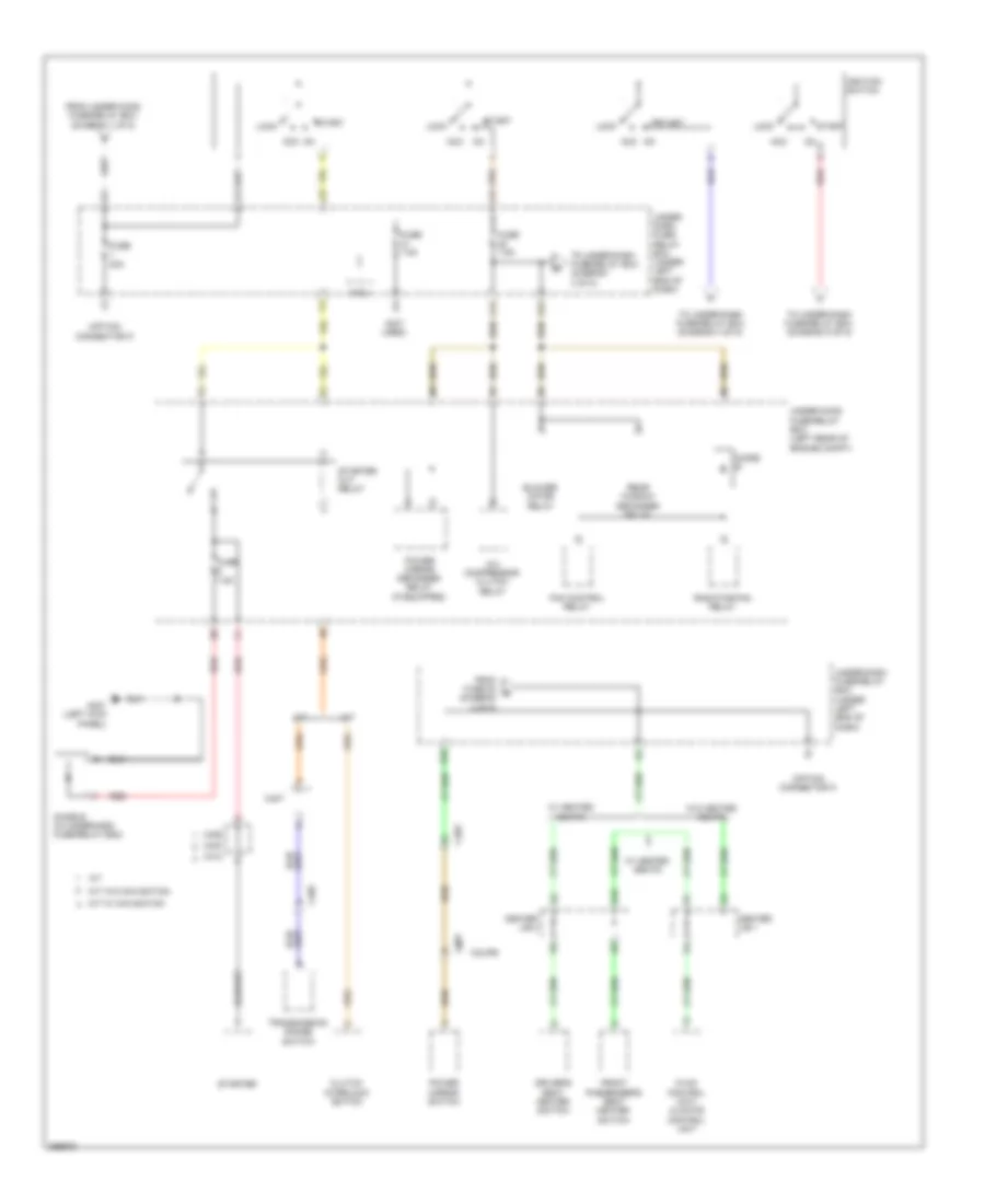
Power Distribution Wiring Diagram, Except Hybrid (2 of 5) for Honda Civic Si 2013
List of elements for Power Distribution Wiring Diagram, Except Hybrid (2 of 5) for Honda Civic Si 2013:
- (not used)
- (under left end of dash) under-dash fuse/relay box
- A16
- Audio unit/ audio- navigation unit
- Automatic lighting/ sunlight sensor (if equipped)
- B10
- B13
- B23
- Battery sensor
- Brake pedal position switch
- C204
- C206
- C214
- C218
- Ceiling light
- Center junction box 1
- Center junction box 2
- D11
- D18
- D28
- Data link connector (dlc)
- Driver's seat heater relay (high) (if equipped)
- Driver's seat heater relay (low) (if equipped)
- From c fuse 11 (diagram 1 of 5)
- From fuse 1-1 a (diagram 1 of 5)
- From fuse 27 b (diagram 1 of 5)
- Front fog light relay
- Front individual map light
- Front passenger's seat heater relay (high) (if equipped)
- Front passenger's seat heater relay (low) (if equipped)
- Fuse 10a
- Fuse 15a
- Fuse 20a
- Fuse 7.5a
- Gauge control module (speedo)
- Gauge control module (tach)
- Hazard warning switch
- Horn relay
- Ignition key switch
- Immobilizer keyless control unit
- Micu
- Multi- information display unit
- N13
- Q16
- Red
- Stereo amplifier (if equipped)
- To console accessory power socket relay (diagram 5 of 5)
- Trunk light
- Under- hood fuse/relay box (left rear of engine compt)
- Under-dash fuse/relay box (under left end of dash)
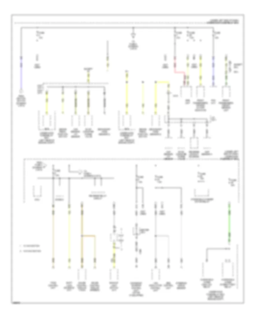
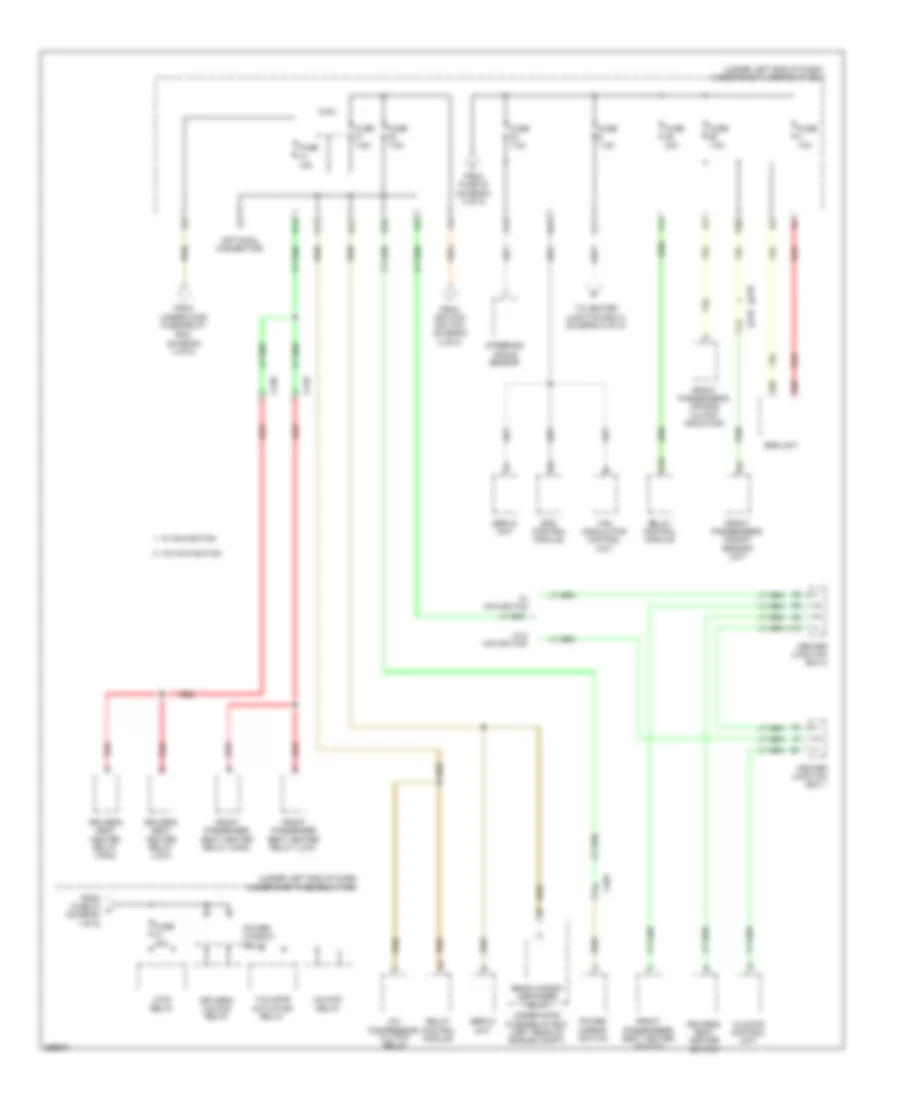
Power Distribution Wiring Diagram, Except Hybrid (3 of 5) for Honda Civic Si 2013
List of elements for Power Distribution Wiring Diagram, Except Hybrid (3 of 5) for Honda Civic Si 2013:
- (not used)
- (option connector f)
- A/c compressor clutch relay
- A/t
- Acc
- Blower motor relay
- C17
- C203
- C301
- C403
- C405
- C406
- C407
- C412
- Center j/b 1
- Center j/b 2
- Clutch interlock switch
- Coupe
- D17
- Diode b
- Diode e (in underhood fuse/relay box)
- Driver's seat heater switch
- Fan control relay
- From fuse 22 e (diagram 3 of 5)
- From under-hood fuse/relay box (diagram 1 of 5)
- Front passenger's seat heater switch
- Fuse 20a
- Fuse 7.5a
- G401 (left kick panel)
- H10
- Hvac control unit/ climate control unit
- Ignition switch
- Lock
- M/t
- M/t w/ navigation
- M/t w/o navigation
- Micu
- On acc
- Power mirror defogger relay (if equipped)
- Power mirror switch
- Radiator fan relay
- Rear window defogger relay
- Red
- S10
- Start
- Starter
- Starter cut relay
- To under-dash fuse/relay box (diagram 3 of 5)
- To under-dash fuse/relay box (diagram 4 of 5)
- To under-dash fuse/relay box (diagram 5 of 5)
- Transmission range switch
- Under- dash fuse/ relay box (under left end of dash)
- Under-dash fuse/relay box (under left end of dash)
- Under-hood fuse/relay box (left rear of engine compt)
- W/ heated seats
- W/o heated seats
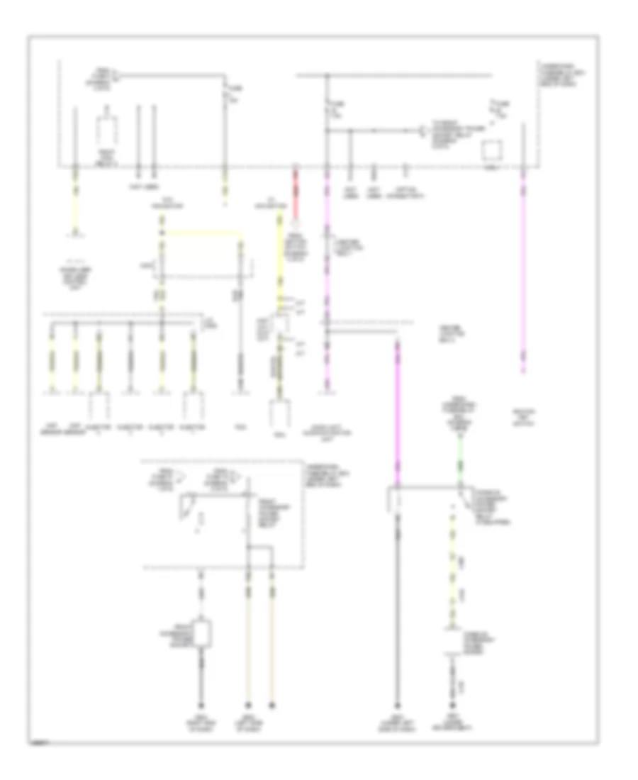
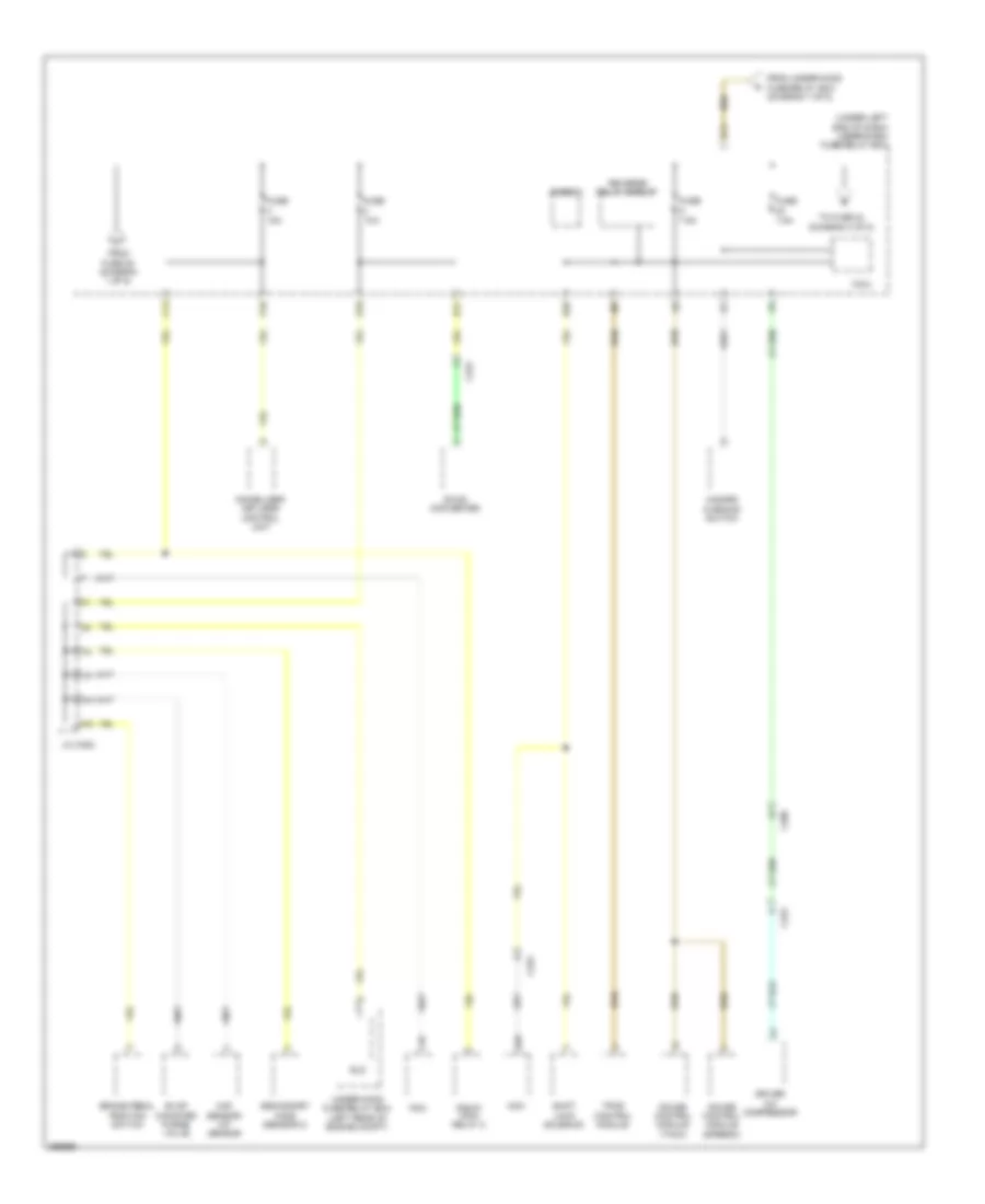
Power Distribution Wiring Diagram, Except Hybrid (4 of 5) for Honda Civic Si 2013
List of elements for Power Distribution Wiring Diagram, Except Hybrid (4 of 5) for Honda Civic Si 2013:
- (not used)
- (under left end of dash) under-dash fuse/relay box
- A38
- A39
- B17
- B28
- B30
- B31
- Backup light switch (m/t)
- Brake pedal position switch
- C206
- C218
- C28
- C36
- C404
- C407 (a/t) c404 (m/t)
- C410
- Center j/b 2
- Cmp sensor a
- D10
- D31
- Diode d
- Eld
- Eps control unit
- Evap canister purge valve
- Ex-l
- Except ex-l
- Except si
- From fuse 2 g (diagram 4 of 5)
- From ignition switch (diagram 3 of 5)
- Front passenger's air bag cutoff indicator
- Front passenger's weight sensor unit
- Fuse 10a
- Fuse 15a
- Fuse 30a
- Fuse 7.5a
- Gauge control module (speedo)
- Gauge control module (tach)
- J/c c011
- K12
- Maf sensor/ iat sensor
- Micu
- Moonroof/ sunroof control unit/ motor (if equipped)
- P15
- Pcm (a/t)
- Q11
- Red
- Reverse lockout solenoid
- Reverse relay circuit
- Secondary ho2s (sensor 2)
- Shift lock solenoid (a/t)
- Srs unit
- Steering angle sensor
- To fuse 4 (diagram 5 of 5)
- To fuse 5 (diagram 4 of 5)
- Tpms control unit
- Under-hood fuse/relay box (left rear of engine compt)
- Vsa modulator control unit
- W/ navigation
- W/o navigation
- Windshield washer motor relay
- Windshield wiper high/low relay
- Windshield wiper intermittent relay
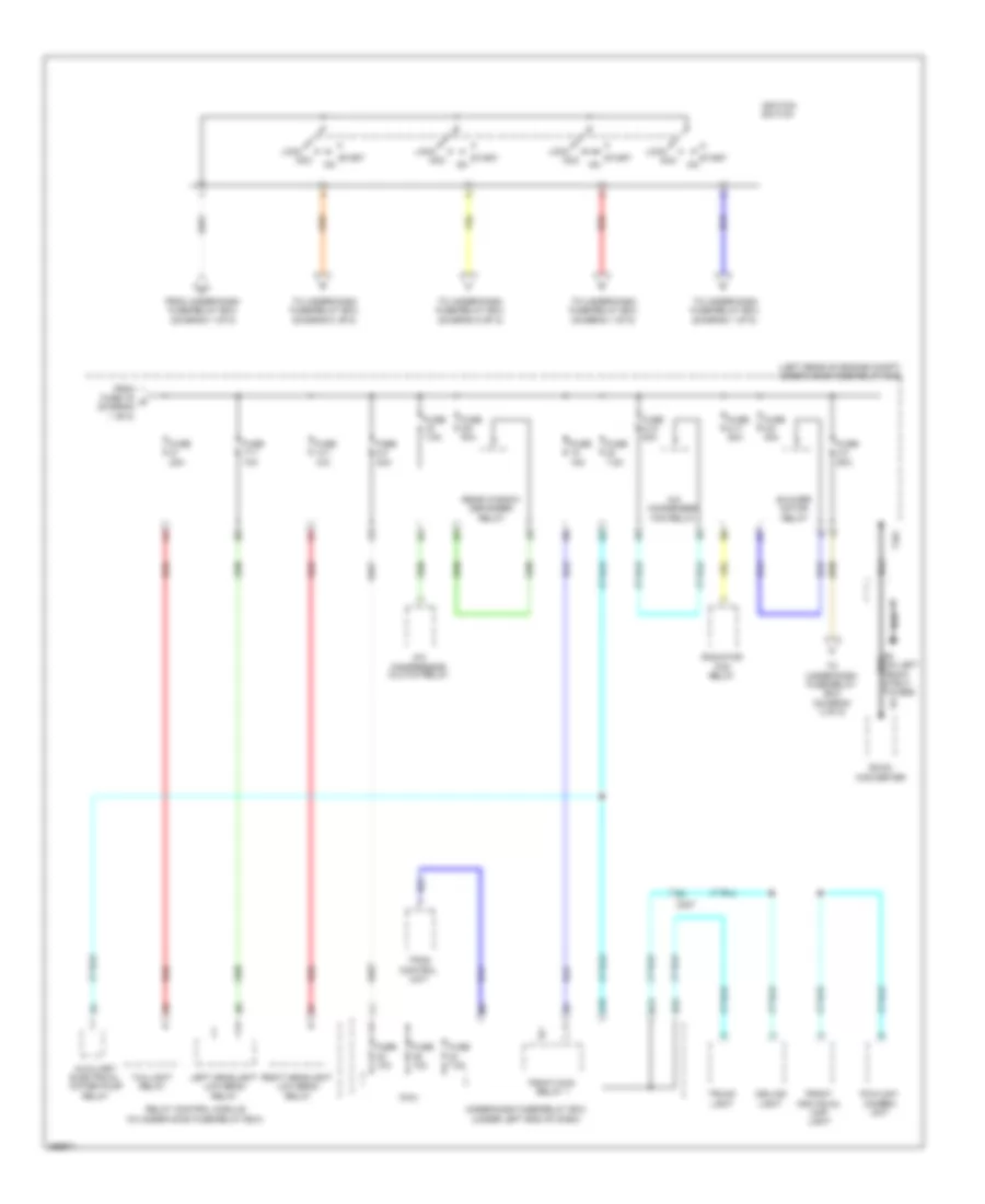
Power Distribution Wiring Diagram, Except Hybrid (5 of 5) for Honda Civic Si 2013
List of elements for Power Distribution Wiring Diagram, Except Hybrid (5 of 5) for Honda Civic Si 2013:
- (not used)
- (option connector f)
- A/t
- A24
- Audio unit/ audio-navigation unit
- B26
- C10
- C13
- C205
- C216
- C404
- C407 (a/t) c410 (m/t)
- Center junction box 1
- Center junction box 2
- Ckp sensor
- Cmp sensor
- Console accessory power socket
- Console accessory power socket relay (if equipped)
- From fuse 19 l (diagram 5 of 5)
- From fuse 27 k (diagram 1 of 5)
- From fuse 5 h (diagram 4 of 5)
- From ignition switch (diagram 3 of 5)
- From under-dash fuse/relay box (diagram 2 of 5)
- Front accessory power socket
- Front accessory power socket relay
- Fuse 15a
- Fuse 7.5a
- G502 (left side of dash)
- G503 (under left side of dash)
- G504 (right end of dash)
- G601 (under driver's seat)
- Ignition key switch
- Immobilizer keyless control unit
- Injector
- J/c c008
- M/t
- Micu
- P14
- P18
- P20
- Pcm
- Pgm-fi main relay 2
- Red
- To front accessory power socket relay (diagram 5 of 5)
- Under-dash fuse/relay box (under left end of dash)
- W/ navigation
- W/o navigation
Power Distribution Wiring Diagram, Hybrid (1 of 5) for Honda Civic Si 2013
List of elements for Power Distribution Wiring Diagram, Hybrid (1 of 5) for Honda Civic Si 2013:
- (left rear of engine compt) under-hood fuse/relay box
- (optional connector f)
- (optional connector)
- 100a
- 10a
- 15a
- 20a
- 30a
- 4 of 5)
- 40a
- 50a
- 60a
- 7.5a
- 70a
- A14
- A16
- A24
- Audio unit/ audio- navigation unit
- Automatic lighting/ sunlight sensor
- B10
- Battery
- Battery sensor
- Brake pedal position switch
- C203
- C206
- C210
- C213
- C217
- C222
- Center junction box 1
- Center junction box 2
- Console accessory power socket
- Console accessory power socket relay
- D12
- D28
- Data link connector
- Eps control unit
- Etcs control relay
- From ignition switch (diagram 4 of 5)
- Front accessory power socket
- Front accessory power socket relay
- Fuse
- Fuse 1-1
- Fuse 1-2
- Fuse 1-3
- Fuse 1-4
- Fuse 1-6
- Fuse 2-1
- Fuse 2-2
- Fuse 2-3
- G502 (left side of dash)
- G503 (left side of dash)
- G504 (right end of dash)
- G601 (under driver's seat)
- Gauge control module (speedo)
- Gauge control module (tach)
- Horn relay
- Ignition key switch
- Immobilizer keyless control unit
- J/c c011 (lower right rear of engine compt)
- Mcm
- Mcm relay 1
- Micu
- Multi- information display unit
- P20
- Power window master switch
- Q16
- Rear window washer motor relay circuit
- Red
- Servo unit
- Starter
- To fuse 21 (diagram
- To fuse 4 (diagram 2 of 5)
- To fuse 41 (diagram 3 of 5)
- To fuse 6 (diagram 5 of 5)
- To ignition switch (diagram 4 of 5)
- To under-dash fuse/relay box (diagram 2 of 5)
- Under-dash fuse/relay box (under left end of dash)
- Vsa modulator control unit
- Windshield washer main relay circuit
Power Distribution Wiring Diagram, Hybrid (2 of 5) for Honda Civic Si 2013
List of elements for Power Distribution Wiring Diagram, Hybrid (2 of 5) for Honda Civic Si 2013:
- (under left end of dash) under-dash fuse/relay box
- 10a
- 15a
- 7.5a
- A29
- B17
- B28
- Brake pedal position switch
- C10
- C13
- C208
- C222
- D10
- D11
- Dc-dc converter
- Diode c
- Driver a/c compressor
- Eld
- Evap canister purge valve
- From fuse 28 (diagram 1 of 5)
- From under-hood fuse/relay box (diagram 1 of 5)
- Fuse
- Gauge control module (speedo)
- Gauge control module (tach)
- Hazard warning switch
- Immobilizer- keyless control unit
- J/c c302
- Maf sensor/ iat sensor
- Mcm
- Micu
- P18
- Pcm
- Pgm-fi main relay 2
- Reverse relay circuit
- Secondary ho2s (sensor 2)
- Shift lock solenoid
- To fuse 24 (diagram 3 of 5)
- Tpms control module
- Under-hood fuse/relay box (left rear of engine compt)
Power Distribution Wiring Diagram, Hybrid (3 of 5) for Honda Civic Si 2013
List of elements for Power Distribution Wiring Diagram, Hybrid (3 of 5) for Honda Civic Si 2013:
- (diagram 4 of 5)
- (optional connector)
- (under left end of dash) under-dash fuse/relay box
- 10a
- 15a
- 20a
- 30a
- 7.5a
- A/c compressor clutch relay
- A16
- A38
- A39
- B13
- B30
- C17
- C203
- C218
- C220
- Center junction box 1
- Center junction box 2
- Climate control unit
- D17
- D31
- Driver's seat heater relay (high)
- Driver's seat heater relay (low)
- Driver's seat heater switch
- Driver's unlock relay
- Eps control module
- From fuse 23 (diagram 2 of 5)
- From fuse 27 h (diagram 1 of 5)
- From ignition switch (diagram 4 of 5)
- From under-hood fuse/relay box
- Front passenger seat heater relay (high)
- Front passenger seat heater relay (low)
- Front passenger's air bag cutoff indicator
- Front passenger's seat heater switch
- Front passenger's weight sensor unit
- Fuse
- H10
- Lock relay
- Micu
- P15
- Power mirror switch
- Power window relay
- Q11
- Rear window defogger relay
- Red
- Relay control module
- S10
- Servo unit
- Srs unit
- Steering angle sensor
- Tailgate actuator relay
- To center junction box 2 (diagram 5 of 5)
- Under-hood fuse/relay box (left rear of engine compt)
- Unlock relay
- Vsa modulator control unit
- W/ navigation
- W/o navigation
Power Distribution Wiring Diagram, Hybrid (4 of 5) for Honda Civic Si 2013
List of elements for Power Distribution Wiring Diagram, Hybrid (4 of 5) for Honda Civic Si 2013:
- (left rear of engine compt) under-hood fuse/relay box
- A/c compressor clutch relay
- A/c condenser fan relay
- Acc
- Auxiliary electrical water pump relay
- B23
- Blower motor relay
- C207
- Ceiling light
- D18
- Dc-dc converter
- Fcw/ldw camera unit
- From fuse 1-6 g (diagram 1 of 5)
- From under-dash fuse/relay box (diagram 1 of 5)
- Front individual map light
- Fuse 10a
- Fuse 14-1 10a
- Fuse 15a
- Fuse 17-1 10a
- Fuse 2-10 20a
- Fuse 2-11 20a
- Fuse 2-3 60a
- Fuse 2-4 30a
- Fuse 2-6 30a
- Fuse 2-8 40a
- Fuse 20a
- Fuse 7.5a
- Ignition switch
- Left headlight low beam relay
- Lock
- Micu
- N13
- Pgm-fi main relay 1
- Radiator fan relay
- Rear window defogger relay
- Red
- Relay control module (in under-hood fuse/relay box)
- Right headlight low beam relay
- Start
- Start on
- T101
- Taillight relay
- To under-dash fuse/relay box (diagram 1 of 5)
- To under-dash fuse/relay box (diagram 3 of 5)
- To under-dash fuse/relay box (diagram 5 of 5)
- Tpms control unit
- Trunk light
- Under-dash fuse/relay box (under left end of dash)
Power Distribution Wiring Diagram, Hybrid (5 of 5) for Honda Civic Si 2013
List of elements for Power Distribution Wiring Diagram, Hybrid (5 of 5) for Honda Civic Si 2013:
- (left rear of engine compt) under-hood fuse/relay box
- (under left end of dash) under-dash fuse/relay box
- 10a
- 15a
- 20a
- 7.5a
- C207
- C216
- C222
- Center junction box 2
- Daytime running lights relay
- Fcw/ldw camera unit
- From fuse 8 m (diagram 1 of 5)
- From ignition switch (diagram 4 of 5)
- From under-dash fuse/relay box (diagram 3 of 5)
- Fuse
- Ignition coil relay
- Ldw off switch
- Mcm relay 2
- N/a
- Pcm
- Pgm-fi sub relay
- Starter cut relay 1
- Sts fuse