POWER DISTRIBUTION
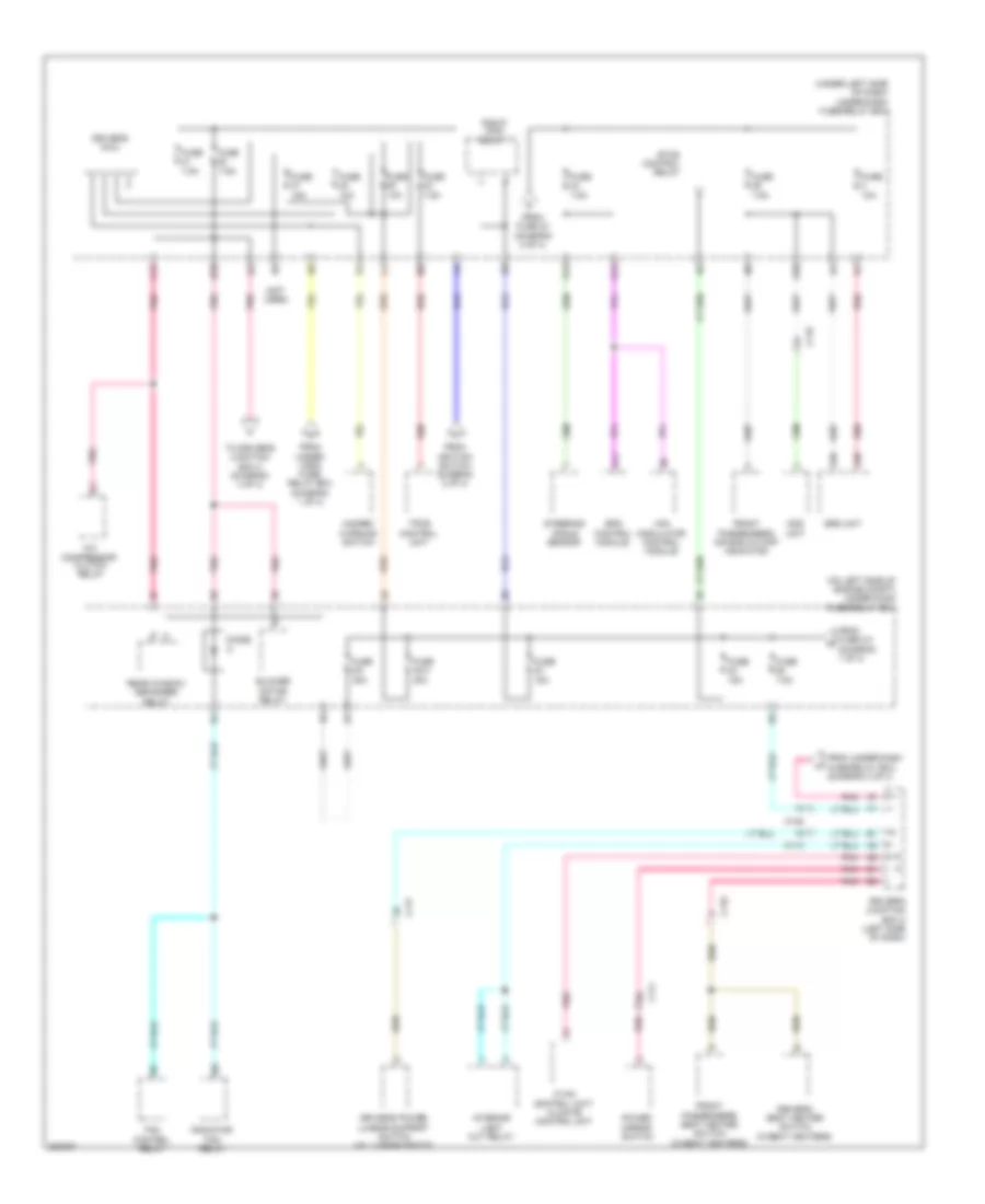
Power Distribution Wiring Diagram (1 of 4) for Honda CR-V EX 2012

List of elements for Power Distribution Wiring Diagram (1 of 4) for Honda CR-V EX 2012:
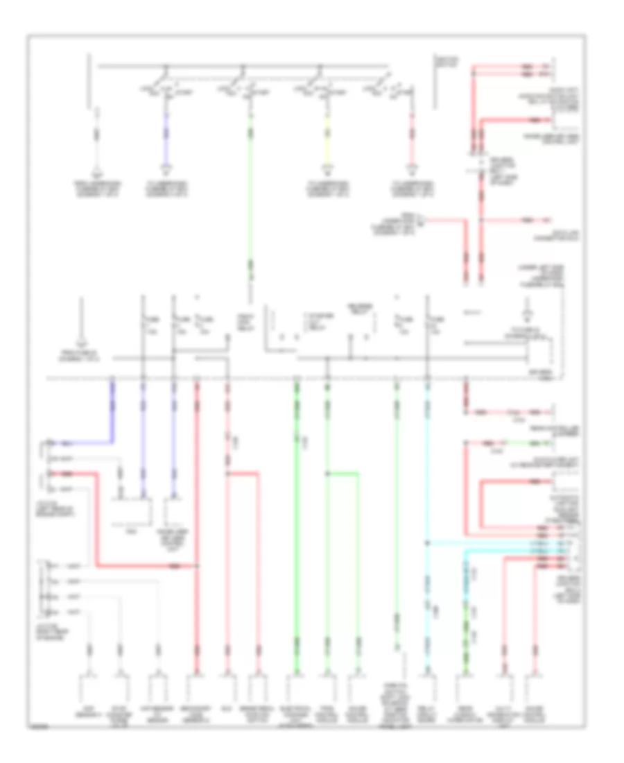
Power Distribution Wiring Diagram (2 of 4) for Honda CR-V EX 2012
List of elements for Power Distribution Wiring Diagram (2 of 4) for Honda CR-V EX 2012:
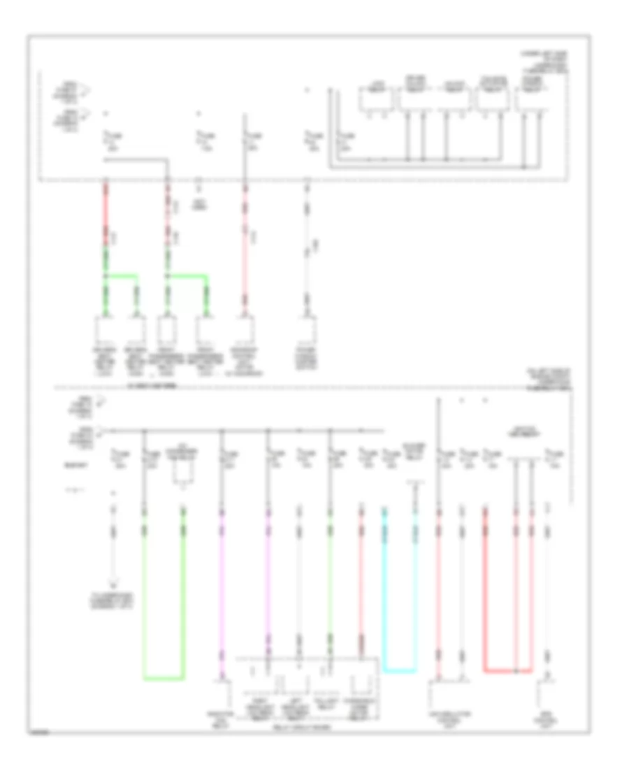
Power Distribution Wiring Diagram (3 of 4) for Honda CR-V EX 2012
List of elements for Power Distribution Wiring Diagram (3 of 4) for Honda CR-V EX 2012:
Power Distribution Wiring Diagram (4 of 4) for Honda CR-V EX 2012
List of elements for Power Distribution Wiring Diagram (4 of 4) for Honda CR-V EX 2012: