POWER DISTRIBUTION
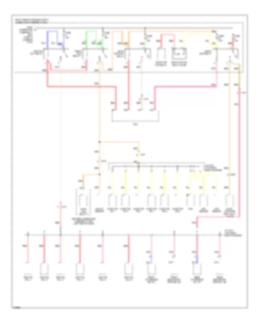
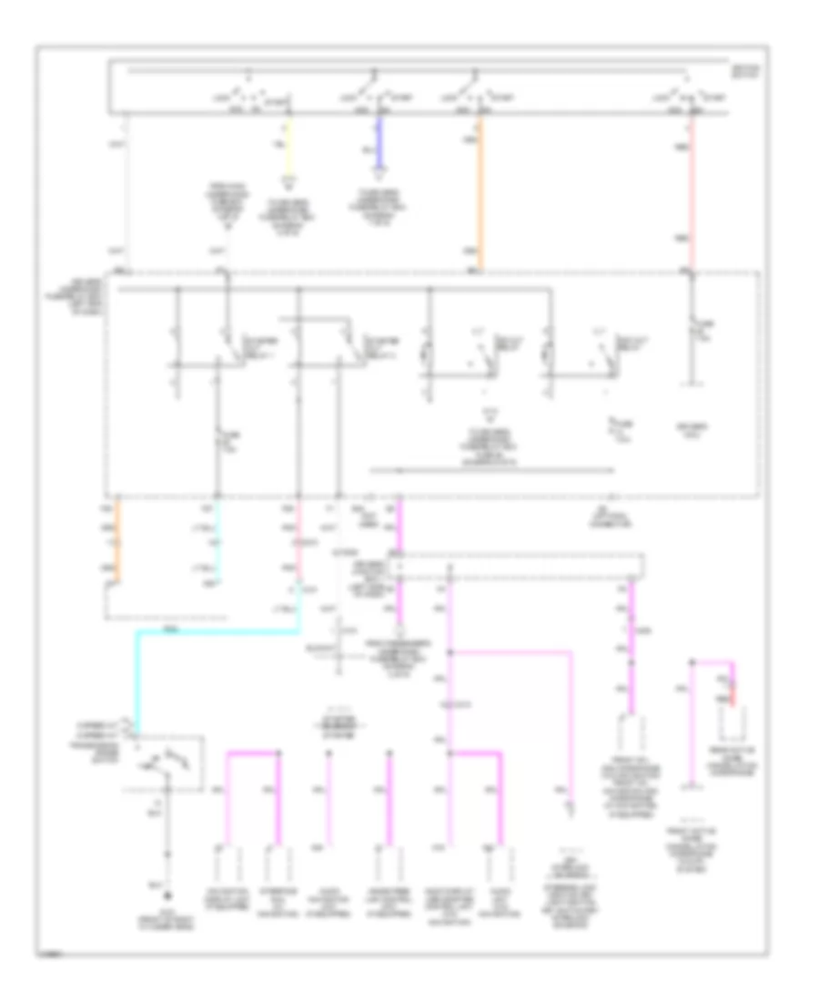
Power Distribution Wiring Diagram (1 of 9) for Honda Odyssey Touring 2013

List of elements for Power Distribution Wiring Diagram (1 of 9) for Honda Odyssey Touring 2013:
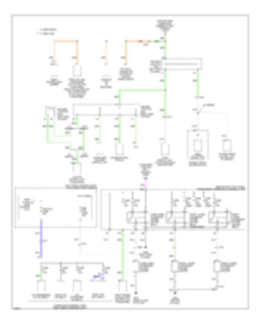
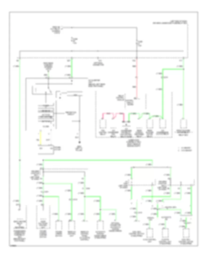
Power Distribution Wiring Diagram (2 of 9) for Honda Odyssey Touring 2013
List of elements for Power Distribution Wiring Diagram (2 of 9) for Honda Odyssey Touring 2013:
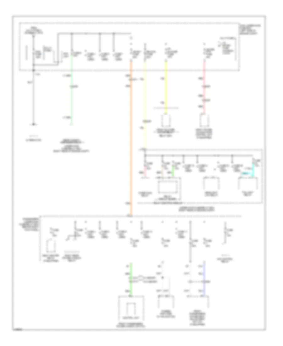
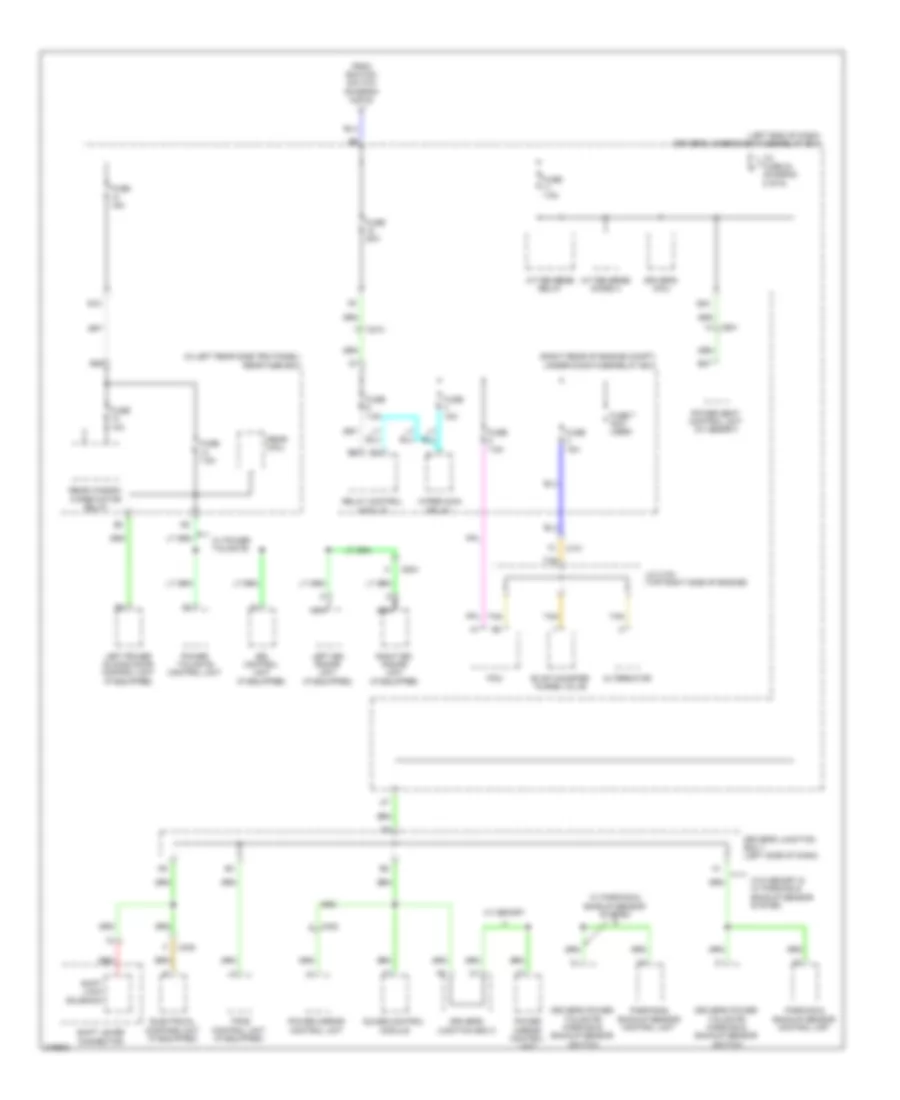
Power Distribution Wiring Diagram (3 of 9) for Honda Odyssey Touring 2013
List of elements for Power Distribution Wiring Diagram (3 of 9) for Honda Odyssey Touring 2013:
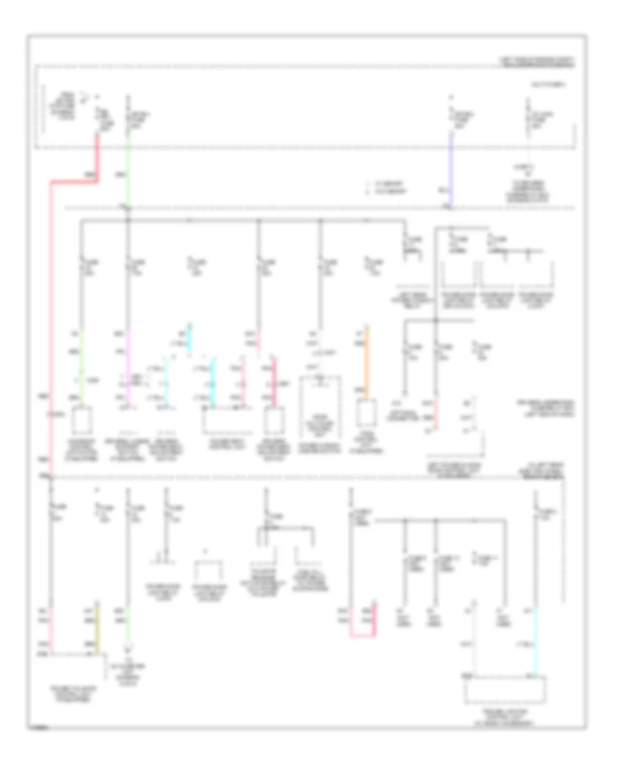
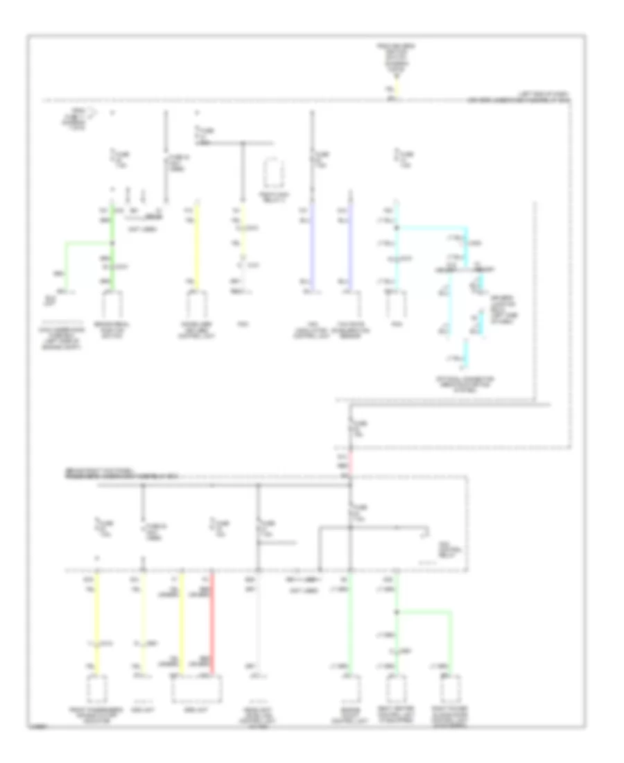
Power Distribution Wiring Diagram (4 of 9) for Honda Odyssey Touring 2013
List of elements for Power Distribution Wiring Diagram (4 of 9) for Honda Odyssey Touring 2013:
Power Distribution Wiring Diagram (5 of 9) for Honda Odyssey Touring 2013
List of elements for Power Distribution Wiring Diagram (5 of 9) for Honda Odyssey Touring 2013:
Power Distribution Wiring Diagram (6 of 9) for Honda Odyssey Touring 2013
List of elements for Power Distribution Wiring Diagram (6 of 9) for Honda Odyssey Touring 2013:
Power Distribution Wiring Diagram (7 of 9) for Honda Odyssey Touring 2013
List of elements for Power Distribution Wiring Diagram (7 of 9) for Honda Odyssey Touring 2013:
Power Distribution Wiring Diagram (8 of 9) for Honda Odyssey Touring 2013
List of elements for Power Distribution Wiring Diagram (8 of 9) for Honda Odyssey Touring 2013:
Power Distribution Wiring Diagram (9 of 9) for Honda Odyssey Touring 2013
List of elements for Power Distribution Wiring Diagram (9 of 9) for Honda Odyssey Touring 2013: