POWER DISTRIBUTION
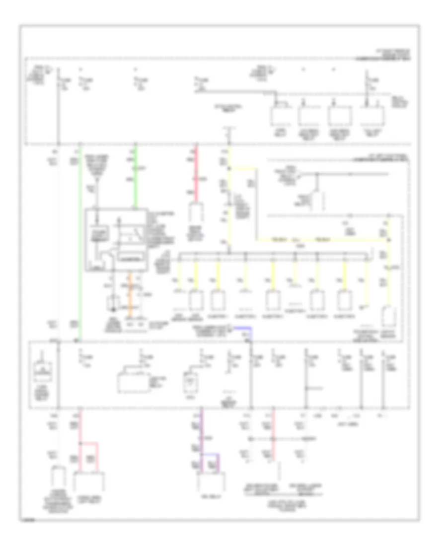
Power Distribution Wiring Diagram (1 of 5) for Honda Ridgeline RTS 2014

List of elements for Power Distribution Wiring Diagram (1 of 5) for Honda Ridgeline RTS 2014:
- (at right rear of engine compt) under-hood fuse/relay box
- (not used)
- (trailer electric brake connector)
- 120a
- 40a
- A/c compressor clutch relay
- A/c condenser fan relay
- Alternator
- Auxiliary under-hood relay box (right front of engine compt)
- Battery
- C302
- C401
- C410
- Cigarette lighter (honda accessory)
- Driver's accessory power socket (except honda accessory)
- Eld unit
- Etcs control
- From under- dash fuse/ d
- From under-dash fuse/relay box (diagram 5 of 5)
- Front accessory power socket relay (left side of dash)
- Front passenger's accessory power socket
- Fuse 15a
- Fuse 20a
- Fuse 30a
- Fuse 40a
- Fuse 7.5a
- G1 (left front of engine compt)
- G401 (left side of dash)
- G402 (right end of dash)
- Moonroof close relay (usa: rtl & se; canada: touring)
- Moonroof open relay (usa: rtl & se; canada: touring)
- Multi- fuse 22
- Radiator fan relay
- Relay
- Relay box (diagram 4 of 5)
- Seat heater relay (usa: rtl & se; canada: sport- se & touring)
- Starter
- Starter solenoid
- T101
- To fuse 16 (diagram 2 of 5)
- To fuse 8 (diagram 3 of 5)
- To low beam headlight relay (diagram 2 of 5)
- To multi- fuse 23 (diagram 3 of 5)
- To under- dash fuse/ relay box (diagram 2 of 5)
- Tpms control unit
- Trailer electric brake (if equipped)
- Trailer lighting control unit
- Trailer lighting relay 1
- Trailer lighting relay 2
- Transmission housing
- Usa: rt sport
- Usa: rts, rtl & se; canada
- Vsa modulator control unit
- Vtm-4 relay
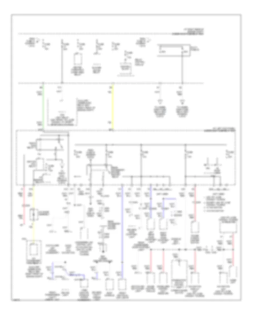
Power Distribution Wiring Diagram (2 of 5) for Honda Ridgeline RTS 2014
List of elements for Power Distribution Wiring Diagram (2 of 5) for Honda Ridgeline RTS 2014:
- (at left kick panel) under-dash fuse/relay box
- (at right rear of engine compt) under-hood fuse/relay box
- (diagram 1 of 5)
- (not used)
- (usa: rts, rtl & se; canada: sport-se & touring)
- +b hazard
- A/c inverter unit (usa: rtl & se; canada: touring) (under front passenger's seat)
- A/f sensor relay
- Ac power outlet
- Ac+
- Ac-
- B21
- Brake pedal position switch
- C201
- C205
- C302
- C503
- C505
- Cargo area light relay
- Ckp sensor
- Cmp sensor
- Cpu
- D14
- D17
- Day lt
- Driver's lumbar support switch
- Driver's power seat adjustment switch
- Drl relay
- Etcs control relay
- F11
- F13
- F19
- From fuse 20 g
- From multi- c
- From pgm-fi main relay 1 s (diagram 3 of 5)
- From under- dash fuse/ relay box (diagram 5 of 5)
- From under-hood fuse/relay box (diagram 1 of 5)
- Fuse (not used)
- Fuse 10a
- Fuse 15a
- Fuse 20a
- Fuse 22 (diagram 1 of 5)
- Fuse 40a
- Fuse 7.5a
- G501 (under center console)
- Hazard warning switch/front passenger's air bag cut-off indicator
- High beam headlight relay
- Horn relay
- Ignition coil relay
- Injector 1
- Injector 2
- Injector 3
- Injector 4
- Injector 5
- Injector 6
- Inverter
- J/c c101 (right side of engine compt)
- J/c c103 (middle rear of engine compt)
- Low beam headlight relay
- Maf/iat sensor
- Micu
- N40
- N45
- Pgm-fi main relay 2
- Powertrain control module (pcm)
- Red
- Relay control module
- Taillight relay
- Turn signal/ hazard relay
- X12
- X23
- X26
- X31
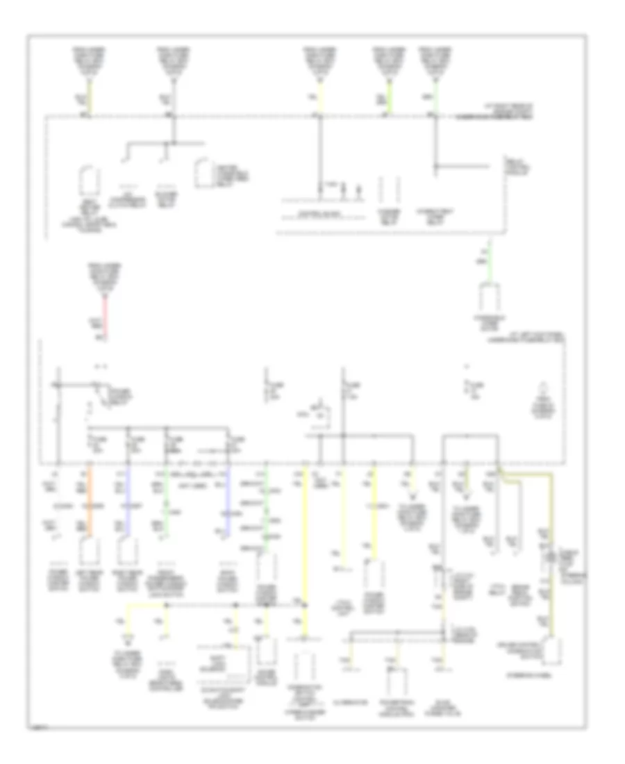
Power Distribution Wiring Diagram (3 of 5) for Honda Ridgeline RTS 2014
List of elements for Power Distribution Wiring Diagram (3 of 5) for Honda Ridgeline RTS 2014:
- (at left kick panel) under-dash fuse/relay box
- (at right rear of engine compt) under-hood fuse/relay box
- (diagram 1 of 5)
- (not used)
- (usa: rtl & se, canada: touring) xm receiver
- +b door lock
- 20a
- 50a
- 60a
- A/c condenser fan relay
- A/c diode assembly
- A/f sensor relay
- A19
- A24
- Audio unit (w/o navigation)
- Auxiliary under-hood relay box (right front of engine compt)
- Blower motor relay
- C402
- C405
- C408
- C453
- C454
- C505
- C505 c505
- C506
- C507
- Canada: touring
- Ceiling light
- Combination switch control unit
- Console box light 1
- Control block
- D10
- D12
- D16
- Dlc
- Driver's door courtesy light
- Driver's vanity mirror light
- Dvd player unit (honda accessory)
- Except usa: rtl & se
- F13
- Fog light relay (usa: sport, rtl & se canada: vp, sport, sport-se & touring)
- From fuse 12 e
- From fuse 19 f
- From fuse 32 (diagram 5 of 5)
- Front individual map lights
- Front passenger's door courtesy light
- Front passenger's vanity mirror light
- Fuse
- Fuse 10a
- Fuse 15a
- Fuse 20a
- Fuse 40a
- Fuse 7.5a
- G401 (left side of dash)
- G501 (under center console)
- Gauge control module
- Handsfree link control unit (w/ navigation: usa: rtl & se; canada: touring)
- Heated windshield
- Ignition coil relay
- Ignition key switch/key light
- Immobilizer control unit- receiver
- Imoes unit
- Left rear door courtesy light
- Micu
- Multi- fuse 23
- N10
- N11
- N15
- N42
- Navigation display unit (usa: rtl & se, canada: touring)
- Navigation unit (usa: rtl & se, canada: touring)
- Pcm
- Pgm-fi main relay 1
- Power window master switch
- Rear accessory power socket
- Rear accessory power socket relay
- Relay control module
- Right rear door courtesy light
- Roof console
- To pgm-fi main relay 2 (diagram 2 of 5)
- To under- dash fuse/ relay box (diagram 4 of 5)
- To under- dash fuse/ relay box (diagram 5 of 5)
- Usa: rtl & se;
- Vbu
- Video monitor console (honda accessory)
- W/ navigation
- W/o navigation
- Wiper area relay
- Wiper/washer switch
- X204
- X22
- X35
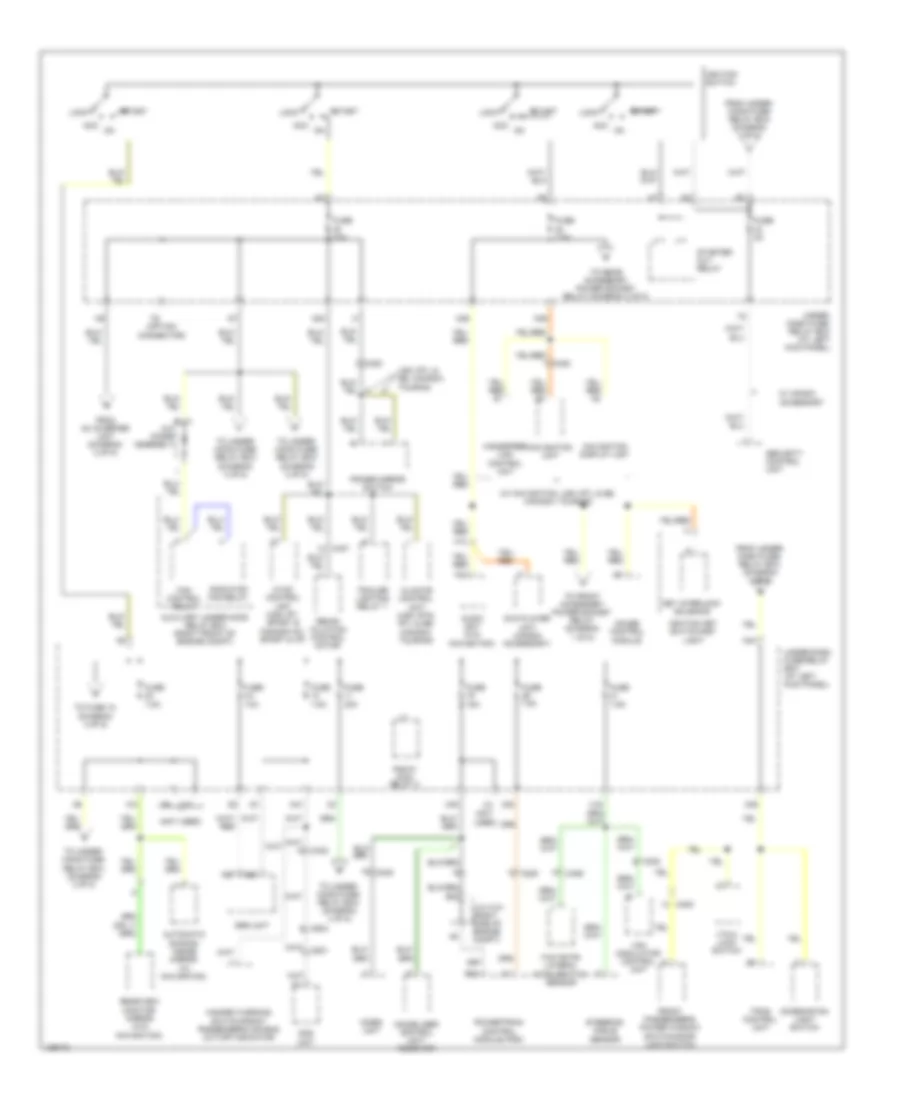
Power Distribution Wiring Diagram (4 of 5) for Honda Ridgeline RTS 2014
List of elements for Power Distribution Wiring Diagram (4 of 5) for Honda Ridgeline RTS 2014:
- (at left kick panel) under-dash fuse/relay box
- (at right rear of engine compt) under-hood fuse/relay box
- (not used)
- A/c compressor clutch relay
- A20
- Alternator
- B13
- B20
- Back power window switch
- Blower motor relay
- Brake pedal position switch
- C13
- C403
- C408
- C454
- C502
- C506
- C507
- Cable reel (top of steering column)
- Combination switch control unit
- Control block
- Cruise control combination switch
- D3 switch/shift lock solenoid/park pin switch
- Dash lights brightness controller
- Evap canister purge valve
- From fuse 20 (diagram 5 of 5)
- From under- dash fuse/ relay box (diagram 4 of 5)
- From under- dash fuse/ relay box (diagram 5 of 5)
- From under- hood fuse/ relay box (diagram 3 of 5)
- Front passenger's power window switch/door lock switch
- Fuse 15a
- Fuse 20a
- Fuse 7.5a
- Gauge control module
- H11
- Heated windshield wiper area relay
- Ig1
- Intermittent wiper relay
- J/c c101 (right side of engine compt)
- J/c c105 (rear of engine)
- Left rear power window switch
- Micu
- N12
- N29
- Power window master switch
- Power window relay
- Powertrain control module (pcm)
- Relay control module
- Right rear power window switch
- Seat heater relay (usa: rtl & se; canada: sport-se & touring)
- Shift lock solenoid
- Steering wheel
- Tan
- To under- dash fuse/ relay box (diagram 5 of 5)
- To under- hood fuse/ relay box (diagram 1 of 5)
- To under- hood fuse/ relay box (diagram 4 of 5)
- Vtm-4 control unit
- Vtm-4 relay
- Washer motor relay
- Windshield wiper motor
- Wiper/washer switch
- X14
- X24
- X34
- X37
- X39
Power Distribution Wiring Diagram (5 of 5) for Honda Ridgeline RTS 2014
List of elements for Power Distribution Wiring Diagram (5 of 5) for Honda Ridgeline RTS 2014:
- (not
- (not used)
- (option connector)
- (w/ navigation, usa: rtl & se; canada: touring)
- A/c diode assembly
- A14
- A26
- A27
- Acc
- Audio unit (w/o navigation)
- Automatic dimming inside mirror (w/ navigation)
- Auxiliary under-hood relay box (right front of engine compt)
- B42
- C205
- C302
- C402
- C406
- C408
- C453
- C504
- Climate control unit (usa: rts, rtl & se; canada: touring)
- Combination light switch
- Dvd player unit (honda accessory)
- Fan control relay
- From ac inverter unit (diagram 2 of 5)
- From under- dash fuse/ relay box (diagram 4 of 5)
- From under- hood fuse/ relay box (diagram 3 of 5)
- Front passenger's power window switch/door lock switch
- Fuse 10a
- Fuse 15a
- Fuse 2a
- Fuse 30a
- Fuse 7.5a
- Gauge control module
- Handsfree link control unit
- Hazard warning switch/front passenger's air bag cut-off indicator
- Hvac control unit (usa: rt, sport & canada: dx, sport & vp)
- Ignition key switch/key light
- Ignition switch
- Immobilizer control unit- receiver
- Imoes unit
- J/c c101 (right side of engine compt)
- Key interlock solenoid
- Lock
- N20
- N36
- N38
- N39
- N41
- N44
- Navigation display unit
- Navigation unit
- Ods unit
- Pgm-fi main relay 2
- Power mirror switch
- Powertrain control module (pcm)
- Radiator fan relay
- Rearview monitor mirror (w/o navigation)
- Recir- culation control motor
- Security control unit
- Srs unit
- Start
- Starter cut relay
- Steering angle sensor
- To front accessory power socket relay (diagram 1 of 5)
- To fuse 18 (diagram 4 of 5)
- To rear accessory power socket relay (diagram 3 of 5)
- To under- hood fuse/ relay box (diagram 4 of 5)
- Tpms control unit
- Trailer lighting relay 1
- Under- dash fuse/ relay box (at left kick panel)
- Under-dash fuse/relay box (at left kick panel)
- Usa: rtl & se; canada: touring
- Used)
- Vsa modulator control unit
- Vtm-4 lock switch
- W/ honda accessory
- X16
- X17
- X20
- X38
- Yaw rate- lateral acceleration sensor