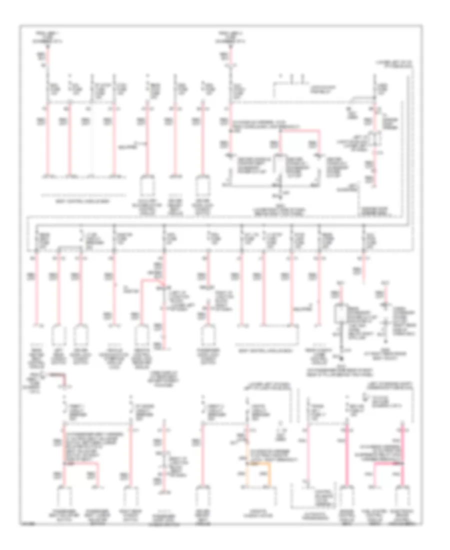
POWER DISTRIBUTION
Power Distribution Wiring Diagram (1 of 4) for Hummer H2 2009

List of elements for Power Distribution Wiring Diagram (1 of 4) for Hummer H2 2009:
- (chassis harness, 8 cm from fuse block underhood x3 breakout) j110
- (infotainment harness in x350 breakout, 6 cm from main harness) j201
- (left of engine compt) underhood fuse block
- (not used)
- (not used) d2
- (part of positive battery cable assembly) battery cable junction block
- 200a
- A5 x3
- Air bag batt fuse 38 15a
- Air suspension control module
- Air suspension relay
- Amp fuse 35 30a
- Audio amplifier
- Automatic transmission
- B3 x3
- Battery
- Bck/up lamp pcb relay
- Blower motor control module
- Body control module (bcm)
- C1 x3
- Clock
- Control solenoid valve assembly
- Crnk relay
- Data link connector (dlc)
- Digital radio receiver (if equipped)
- Dlis fuse 29 2a
- Drl pcb relay
- E2 x4
- Ecas fuse 32 15a
- Ecas fuse 51 60a
- Ecm batt fuse 10 10a
- Electronic brake control module (ebcm)
- Engine control module (ecm)
- Evaporative emission (evap) canister vent solenoid valve
- F1 x5
- Front accessory power outlet
- Frt wash pcb relay
- Fuel fuse 18 20a
- Fuel pump flow control module
- G203 (lower right side of dash, behind right kick panel)
- G3 x4
- Generator
- Hdlp lo relay
- Hi beam pcb relay
- Horn pcb relay
- Hvac batt fuse 33 10a
- Hvac blwr fuse 61 40a
- Hvac control module
- Inflatable restraint sensing & diagnostic module (sdm)
- Inflatable restraint vehicle rollover sensor
- Inline fuse generator
- Instrument panel cluster (ipc)
- Ipc fuse 39 10a
- J215
- Lbec 1 fuse 56 60a
- Lbec 2 fuse 62 60a
- Left i/p junction block (lower left of dash)
- Ltr fuse 44 15a
- Mbec 1 fuse 60 60a
- Nca
- Prk lamp relay
- Radio
- Rdo fuse 36 15a
- Rear defog relay
- Rear seat audio (rsa) control
- Rear wash pcb relay
- Red
- Right i/p junction block (right of dash)
- S/roof fuse 28 30a
- Security indicator lamp
- Seo b1 fuse 43 15a
- Seo b2 fuse 31 30a
- Starter
- Stud 1 trlr fuse 59 40a
- Stud 2 trlr fuse 55 30a
- Sunroof module (if equipped)
- Tcm batt fuse 12 15a
- To i/p fuse block (diagram 2 of 4)
- To left i/p junction block (diagram 2 of 4)
- To run/accy pcb relay (diagram 3 of 4)
- To splice j212 (diagram 4 of 4)
- Trailer connector
- Transfer case shift control module
- Trec fuse 58 30a
- Trlr stop lt pcb relay
- Trlr stop rt pcb relay
- Vehicle inclination sensor
- Vehicle shock sensor
- Vses/ abs 1 fuse 52 60a
- Vses/ abs 2 fuse 7 30a
- W/ off road suspension chassis package
- W/ speedometer theft
- Wiper control pcb relay
- Wiper speed pcb relay
- Wpr fuse 30 25a
- X11
- X2 d3
- X2 n3
- X3 e4
- X4 e1
- X4 j1
- X5 b2
- X5 d
- X5 d1
- X5 f2
- X6 a
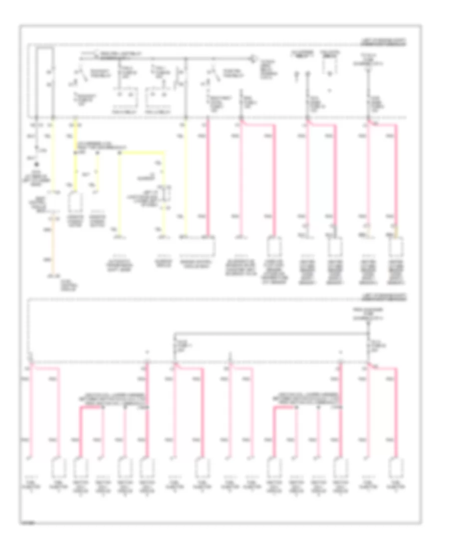
Power Distribution Wiring Diagram (2 of 4) for Hummer H2 2009
List of elements for Power Distribution Wiring Diagram (2 of 4) for Hummer H2 2009:
- (in chassis harness, 20 cm from air suspension relay main harness breakout) j356
- (in console harness, 16 cm from console bin lamp breakout) j352
- (in midgate harness 10 cm from midgate latch - right breakout) j334
- (left of engine compt) underhood fuse block
- (lower left of dash) left i/p junction block
- (lower left of i/p) i/p fuse block
- (not used)
- A1 x4
- A7 x3
- Automatic transmission
- Aux pwr 2 fuse 20a
- Aux pwr fuse 20a
- Auxiliary blower motor control module
- B1 x2
- B4 x4
- B7 x2
- Bcm fuse 10a
- Body control module (bcm)
- Cargo accessory power outlet (right rear side of cargo box)
- Center console 1 accessory power outlet
- Center console 2 accessory power outlet
- Center console compartment accessory power outlet
- Control solenoid valve assembly
- Ctsy fuse 15a
- D1 x1
- Ddm fuse 15a
- Dim fuse 10a
- Driver door lock/ window switch
- Driver memory seat module
- Dseat 2 circuit breaker 25a
- Dsm fuse 10a
- Ecm ign fuse 47 15a
- Electronic brake control module (ebcm)
- Engine control module (ecm)
- F5 x3
- From c mbec 1 fuse (diagram 1 of 4)
- From lbec 1 fuse (diagram 1 of 4)
- From lbec 2 fuse (diagram 1 of 4)
- Fuel system control module (fscm)
- G2 x1
- G203 (lower right side of dash, behind right kick panel)
- G405 (at right rear frame body mount)
- G410 (on passenger side rear of body near "d" pillar behind trim panel)
- Garage door opener (gdo)
- If equipped
- Info fuse 5a
- Int lts fuse 10a
- J410
- Left i/p junction block (lower left of dash)
- Left rear window switch
- Left sunshade
- Lock/unlock pcb relay
- Lt dr circuit breaker 25a
- Lt stop turn fuse 15a
- Mgate circuit breaker 25a
- Midgate window motor
- Onstar fuse 10a
- P5 x2
- Passenger door lock/ window switch
- Passenger seat adjuster switch
- Passenger seat lumbar adjuster switch
- Pdm fuse 15a
- Pnk
- Pseat 1 circuit breaker 25a
- Rear accessory power outlet (mounted in the trim panel below right d-pillar)
- Rear heated seat control module
- Rear hvac fuse 30a
- Rear seat fuse 20a
- Rear window wiper control module
- Rear wiper fuse 25a
- Remote control door lock receiver (rcdlr)
- Right i/p junction block (right of dash)
- Right rear window switch
- Rt doors circuit breaker 25a
- Rt stop turn fuse 15a
- Stop lamp fuse 15a
- Sut
- Suv
- To hvac ign fuse (diagram 4 of 4)
- Trans ign 1 fuse 17 15a
- Ugdo fuse 10a
- Vehicle communication interface module (vcim)
- Video display (w/ rear seat entertainment package)
- W/ garage door opener
- W/ onstar
- X1 3b2
- X1 3b4
- X1 f1
- X1 j2
- X10
- X11
- X12
- X2 a4
- X2 b5
- X3 b2
- X3 b4
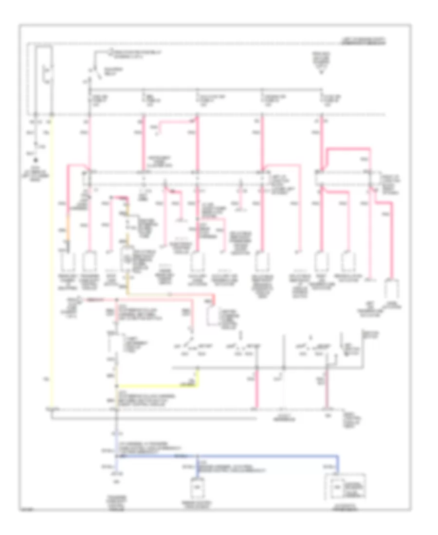
Power Distribution Wiring Diagram (3 of 4) for Hummer H2 2009
List of elements for Power Distribution Wiring Diagram (3 of 4) for Hummer H2 2009:
- (i/p harness, 5 cm from the x205 breakout) j220
- (ignition coil jumper harness, between ignition coils 4 & 2, 3 cm from ignition coil 4 breakout) j160
- (ignition coil jumper harness, between ignition coils 5 & 7, 3 cm from ignition coil 5 breakout) j140
- (left of engine compt) underhood fuse block
- A/c cmprsr relay
- Automatic transmission shift lever
- Body control module (bcm)
- Ecm/throt cntrl fuse 3 15a
- Eng fuse 2 15a
- Engine control module (ecm)
- Evaporative emission (evap) canister vent solenoid valve
- Fan 1 fuse 50 40a
- Fan 2 fuse 53 40a
- Fan cntrl relay
- Fan hi relay
- Fan lo relay
- From o2-b snsr fuse (diagram 3 of 4)
- From prk lamp relay (diagram 1 of 4)
- Fuel injector
- G104 (at rear of left cylinder head)
- Heated oxygen sensor (ho2s) bank 1 sensor 1
- Heated oxygen sensor (ho2s) bank 1 sensor 2
- Heated oxygen sensor (ho2s) bank 2 sensor 1
- Heated oxygen sensor (ho2s) bank 2 sensor 2
- Hvac control module
- Ignition coil/ module
- Inj a fuse 20 20a
- Inj b fuse 11 20a
- J102
- Left i/p junction block (lower left of dash)
- Mass air flow (maf) sensor/ intake air temperature (iat) sensor
- Midgate window motor
- Midgate window switch
- N5 x2
- O2-a snsr fuse 16 10a
- O2-b snsr fuse 6 10a
- Pnk
- Pwr/trn pcb relay
- Run/accy fuse 40 10a
- Run/accy pcb relay
- Sunroof module
- Sut
- To inj-a fuse (diagram 3 of 4)
- To run/ crnk relay (diagram 4 of 4)
- W/ sunroof
- X5 d4
Power Distribution Wiring Diagram (4 of 4) for Hummer H2 2009
List of elements for Power Distribution Wiring Diagram (4 of 4) for Hummer H2 2009:
- & body control module)
- (i/p harness, in transfer case control module breakout, 7 cm from breakout) j234
- (left of engine compt) underhood fuse block
- (not used)
- 5-volt reference
- 7.5a
- Acc
- Air bag ign fuse 34 10a
- Automatic transmission
- Aux hvac ign fuse 41 10a
- Auxiliary air temperature actuator
- Auxiliary mode actuator
- Body control module (bcm)
- Control solenoid
- Electronic compass module
- Engine control module (ecm)
- Engine control module breakout)
- From ecm ign fuse (diagram 2 of 4)
- From h dlis fuse diagram 1 of 4)
- From pwr/trn pcb relay (diagram 3 of 4)
- G104 (at rear of left cylinder head)
- Heated steering wheel control module
- Heated steering wheel inline fuse
- Hvac ign fuse 46 10a
- Ign
- Ignition switch
- Inflatable restraint i/p module disable switch
- Inflatable restraint passenger air bag on/off indicator
- Inflatable restraint sensing & diagnostic module (sdm)
- Inflatable restraint steering wheel module coil
- Inside rearview mirror (isrvm)
- Instrument panel cluster (ipc)
- J102
- J236 (dash harness)
- J441 (rear pnk hvac harness)
- Key ignition switch
- Left air temperature actuator
- Left i/p junction block (lower left of dash)
- Misc ign fuse 37 10a
- Mode actuator
- N5 x2
- Nca
- Off
- Pnk
- Rearview camera (if equipped)
- Recirculation actuator
- Red
- Right air temperature actuator
- Right i/p junction block (right of dash)
- Run
- Run/crnk relay
- Seo fuse 45 10a
- Start
- Stop lamp switch
- Theft deterrent module (tdm)
- Transfer case shift control module
- Valve assembly
- W/ air conditioner rear hvac system
- X11
- X12
- X2 a1