POWER DISTRIBUTION
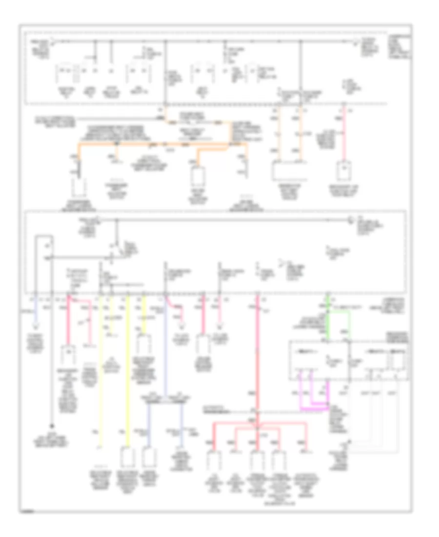
Power Distribution Wiring Diagram (1 of 4) for Hummer H3T 2010

List of elements for Power Distribution Wiring Diagram (1 of 4) for Hummer H3T 2010:
- (above left front wheelwell) underhood fuse block
- (behind right rear quarter trim, near wheelwell) g340
- (in body harness, approximately 2 cm before breakout to x125)
- (in front view camera body harness) j326
- (in i/p harness, approximately 2.5 cm to right of data link connector in main bundle) j214
- (on right inner front wheel- well) g106
- (on right inner front wheelwell) g106
- A/t
- Abs/ vses2 -sol fuse 64 30a
- Abs/vses1 -mtr fuse 67 40a
- Amp fuse 38 25a
- Audio amplifier
- Automatic transmission shift lever
- Aux pwr 1/cig ltr fuse 51 20a
- Aux pwr 2/cig ltr fuse 45 20a
- B10
- Battery
- Bck/ up relay
- Bck/up fuse 60 15a
- Bcm fuse 10a
- Body control module (bcm)
- Clstr fuse 19 10a
- Cnstr vent fuse 31 10a
- Data link connector (dlc)
- Driver door lock/ window switch
- Driver heated seat control module
- E-brake fuse 83 30a
- Electronic brake control module (ebcm)
- Engine control module (ecm)
- Evaporative emission (evap) canister vent solenoid valve
- From b aux pwr 1/ cig ltr fuse 51 (diagram 1 of 4)
- From rear trn/ c hazrd fuse 20 (diagram 1 of 4)
- Frontview camera image display module
- Frt trn/ hazrd/ ctsy mir fuse 56 15a
- Fscm fuse 54 20a
- Fuel pump flow control module
- Gen fuse 91 125a
- Generator
- Htd/seats fuse 1 20a
- Hvac control module
- I/p accessory power outlet 1
- I/p accessory power outlet 2
- Inside rearview mirror (isrvm)
- Instrument panel cluster (ipc)
- J143
- J158 (in breakout to front view camera power harness)
- J205
- J228 (in breakout to body harness)
- Left rear window switch
- Lt pwr wndw fuse 68 30a
- Passenger door lock/ window switch
- Passenger heated seat control module
- Pcm cntrl relay
- Pcm-b fuse 25 10a
- Premium audio
- Pwr s/roof fuse 57 30a
- Pwr/ lks fuse 8 20a
- Radio
- Radio fuse 13 10a
- Rap/ accy relay
- Rear accessory power outlet
- Rear trn/ hazrd fuse 20 20a
- Rear window washer fluid pump
- Rear window wiper control module
- Rear wpr mtr fuse 15 15a
- Rear wpr sw/pump fuse 16 15a
- Red
- Right rear window switch
- Rt pwr wndw fuse 63 30a
- S/roof frt wpr pump fuse 9 15a
- Spo fuse 10 10a
- Starter motor
- Stop fuse 50 15a
- Stop lamp switch
- Strtr fuse 30a
- Sunroof module
- Sunroof motor
- Suv
- Tccm fuse 12 30a
- Tcm pwr fuse 26 10a
- To j270 (diagram 4 of 4)
- To pwr/ loks fuse 8 (diagram 1 of 4)
- To pwr/trn relay 81 (diagram 2 of 4)
- To rap/ accy relay (diagram 1 of 4)
- To vehicle communication interface module (vcim) inline fuse (diagram 4 of 4)
- Trailer connector
- Trans- mission control module (tcm)
- Transfer case shift control module
- Trlr b+ fuse 84 30a
- Turn signal/multi- function switch
- Underhood fuse block (above left front wheelwell)
- W/ electric sun, glass & sliding roof
- W/ hd truck trailer wiring harness
- Windshield wiper/washer switch
- X125
- X150
- X200
- X201
- X204
- X206
- X315
- X420
- X450
- X500
- X600
- X700
- X800
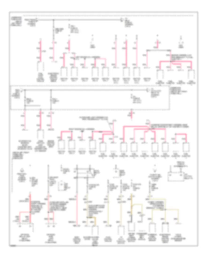
Power Distribution Wiring Diagram (2 of 4) for Hummer H3T 2010
List of elements for Power Distribution Wiring Diagram (2 of 4) for Hummer H3T 2010:
- (3.7l)
- (5.3l)
- (in driver seat harness, approximately 28.5 cm back from x307) j312
- (in passenger seat harness, approximately 10 cm before breakout to seat adjuster & lumbar adjuster/heater switches) j341
- 1-2 shift solenoid (ss) valve
- 2-3 shift solenoid (ss) valve
- A/t
- Air pump fuse 62 60a
- Air pump rly
- Automatic transmission
- Automatic transmission input shaft speed (iss) sensor
- Cool fans fuse 62 40a
- Cruise control release switch
- Cruise/misc fuse 35 10a
- Driver seat adjuster switch
- Driver seat lumbar adjuster switch
- Drl fuse 39 10a
- Drl relay 79
- Fog lamp relay
- From air e pump fuse 62 (diagram 2 of 4)
- From rap/ d accy relay 88 (diagram 1 of 4)
- Frt fog lmp relay 69
- Frt/wpr fuse 25a
- Fuse 1 20a
- Fuse 10a
- Fuse 2 20a
- G105 (on left inner front wheelwell, behind battery)
- Generator battery control module
- Hdlp relay
- Horn relay
- I/p multi- function switch
- Inflatable restraint front passenger presence system (pps) sensor
- Inflatable restraint sensing & diagnostic module (sdm)
- Inflatable restraint vehicle rollover sensor
- Inside rearview mirror (isrvm)
- Inside rearview mirror (isrvm) connector
- J123 (in auxiliary power relay jumper harness)
- J124 (in auxiliary power relay jumper harness)
- J125 (inside auxiliary power relay jumper harness)
- J133
- Nca
- Not used
- Passenger seat adjuster switch
- Passenger seat lumbar adjuster switch
- Pnk
- Power seat fuse holder
- Pwr seats fuse 61 40a
- Pwr/trn relay
- Rear vision fuse 18 10a
- Red
- Relay 1
- Relay 2
- Relay 3
- Run/ crnk relay
- Rvc pwr fuse 7 10a
- Rvc snsr fuse 32 10a
- Seat circuit breaker 25a
- Secondary air injection (air) pump relay
- Secondary air injection (air) pump relay (w/ air injection electric reactor system)
- Secondary underhood fuse block
- Sir fuse 27 10a
- Stop relay 66 (truck)
- Tcm
- To abs/vses fuse 29 (diagram 3 of 4)
- To body control module (diagram 4 of 4)
- To j159 (diagram 4 of 4)
- To j272 (diagram 4 of 4)
- To run/ crank relay 78 (diagram 2 of 4)
- To spo grille guard fuse 2 (diagram 3 of 4)
- Torque converter clutch (tcc) pulse width modulation (pwm) solenoid valve
- Torque converter clutch (tcc) solenoid valve
- Trans fuse 34 10a
- Trans- mission control module (tcm)
- Underhood fuse block (above left front wheelwell)
- W/ air injection electric reactor system
- W/ front view camera
- W/ heavy duty
- W/ multi directional driver front power seat adjuster
- W/ multi directional passenger power seat adjuster
- W/o front view camera
- X125
- X200
- X315
Power Distribution Wiring Diagram (3 of 4) for Hummer H3T 2010
List of elements for Power Distribution Wiring Diagram (3 of 4) for Hummer H3T 2010:
- (3.7l) (5.3l)
- (above left front wheelwell) underhood fuse block
- (if equipped)
- (in blower motor resistor jumper harness, approximately 15 cm from x203) j220
- (in body harness, approximately 5 cm before breakout to ebcm) j141
- (in dealer installed off road harness, 1.5 cm from roof lamps relay, near master cylinder) j101
- (in engine compartment harness, near grille lamps relay, by master cylinder) j103
- (in engine compt harness, near grille lamps relay, by master cylinder) j103
- (in forward lamp harness 5 cm from the breakout to x103)
- (left engine coil harness) j113
- (not used)
- (right engine coil harness) j116
- 3.7l
- 5.3l
- A/c clutch/ relay 76
- A26
- Abs/vses fuse 29 10a
- Air sol fuse 44 15a
- Air sol relay
- Blower motor
- Blower motor high speed relay
- Body control module (bcm)
- C11
- Driver seat lumbar adjuster switch
- Electronic brake control module (ebcm)
- Engine control module (ecm)
- Erls fuse 22 15a
- Evaporative emission (evap) canister vent solenoid valve
- From cool fans fuse 62 (diagram 2 of 4)
- From inj fuse 23 (diagram 3 of 4)
- From o ign-1 fuse 33 (diagram 3 of 4)
- From trans f fuse 34 (diagram 2 of 4)
- Fuel injector
- Fuel pump flow control module
- Hvac blwr fuse 82 30a
- Hvac cntrl hd fuse 59 10a
- Hvac control module
- Hvac relay
- I/p multi- function switch
- Ign-1 fuse 33 15a 20a
- Ignition coil 1
- Ignition coil 2
- Ignition coil 2 (3.7l)
- Ignition coil 3
- Ignition coil 3 (3.7l)
- Ignition coil 4
- Ignition coil 5
- Ignition coil 5 (3.7l)
- Ignition coil 6
- Ignition coil 7
- Ignition coil 8
- Inj fuse 23 15a 20a
- J118
- Mass air flow (maf)/ intake air temperature (iat) sensor
- Nca
- Off road grille lamp relay (if equipped)
- Off road roof lamp relay
- Passenger seat belt buckle
- Pcm 1 fuse 21 10a
- Pnk
- Pnk (engine harness, 5 cm from breakout to fuel injector 1) j111
- Pwr htr sw fuse 53 10a
- Rear defog relay
- Red
- Spo grille guard fuse 2 20a
- Spo roof rack lights fuse 4 20a
- Steering wheel position sensor
- Tccm switch fuse 58 10a
- To a/c clutch relay 76 (diagram 3 of 4)
- To batt ign switch fuse 5 (diagram 4 of 4)
- To erls fuse 22 (diagram 3 of 4)
- Underhood fuse block (above left front wheelwell)
- Vses/ abs fuse 52 10a
- X1 d
- X150
- X200 a3
- X200 d8
- Yaw & lateral accelerometer sensor
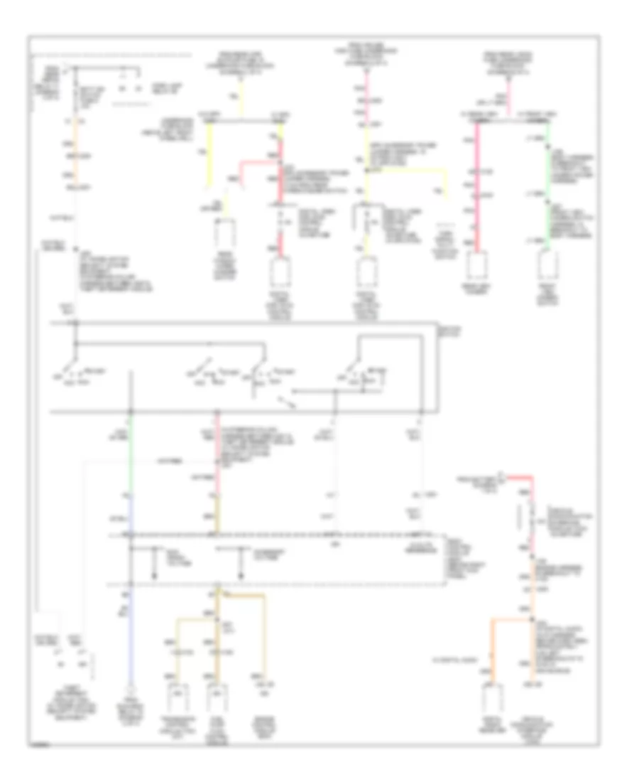
Power Distribution Wiring Diagram (4 of 4) for Hummer H3T 2010
List of elements for Power Distribution Wiring Diagram (4 of 4) for Hummer H3T 2010:
- (a/t)
- (in steering column harness between x201 & red
- (w/ spo dvd2) j272
- 10a
- 5-volts reference
- A14
- Acc
- Accessory voltage
- Batt ign switch fuse 5 10a
- Body control module (bcm) (behind right front kick panel)
- Digital radio receiver
- Digital video disc (dvd) control module
- Digital video disc (dvd) control module inline fuse
- Digital video disc (dvd) control module inline fuse (w/ spo dvd2)
- Engine control module (ecm)
- From battery a (diagram 1 of 4)
- From cruise/ misc fuse (underhood fuse block) (diagram 2 of 4)
- From k rear defog relay 71 (diagram 3 of 4)
- From rear vision fuse (underhood fuse block) (diagram 2 of 4)
- From rear wpr sw/pump fuse 16 (underhood fuse block) (diagram 1 of 4)
- From run/crnk relay 78 (diagram 2 of 4)
- Front view camera switch
- Fuel pump flow control module
- Ign
- Ignition switch
- J106 (engine harness, on breakout to x130)
- J159 (body harness, in breakout to front view camera power harness)
- J200 (w/ immobilization security system equipment) (in steering column harness between x200 & theft deterrent module)
- J207
- J227 (front view camera switch harness, in breakout to body harness)
- J234 (w/ digital audio) (in i/p harness center dash area, approximately 5 cm left of breakouts to hvac in main bundle)
- J270 (spo accessory power jumper harness, 10 cm from rear wiper/washer switch)
- Off
- Park lamp relay 89
- Pnk
- Rear view camera
- Rear window wiper/ washer switch
- Red
- Run
- Run/ crank voltage
- Start
- Theft deterrent module (tdm) (w/ immobilization security system equipment)
- Theft deterrent module) (w/ immobilization security system equipment) j201
- Transmision control module (tcm) (a/t)
- Turn signal/ multi- function switch
- Underhood fuse block (above left front wheelwell)
- Vehicle communication interface module (vcim)
- Vehicle communication interface module (vcim) inline fuse
- W/ digital audio
- W/ front view camera
- W/ rear view camera
- W/ spo dvd1
- W/o spo dvd1
- X102
- X150
- X2 a42
- X200
- X200 b8
- X200 b9
- X201 a8
- X201 b1
- X201 b3
- X420