POWER DISTRIBUTION
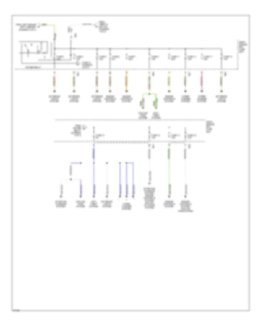
Power Distribution Wiring Diagram (1 of 4) for Jaguar XJ6 Vanden Plas 1995

List of elements for Power Distribution Wiring Diagram (1 of 4) for Jaguar XJ6 Vanden Plas 1995:
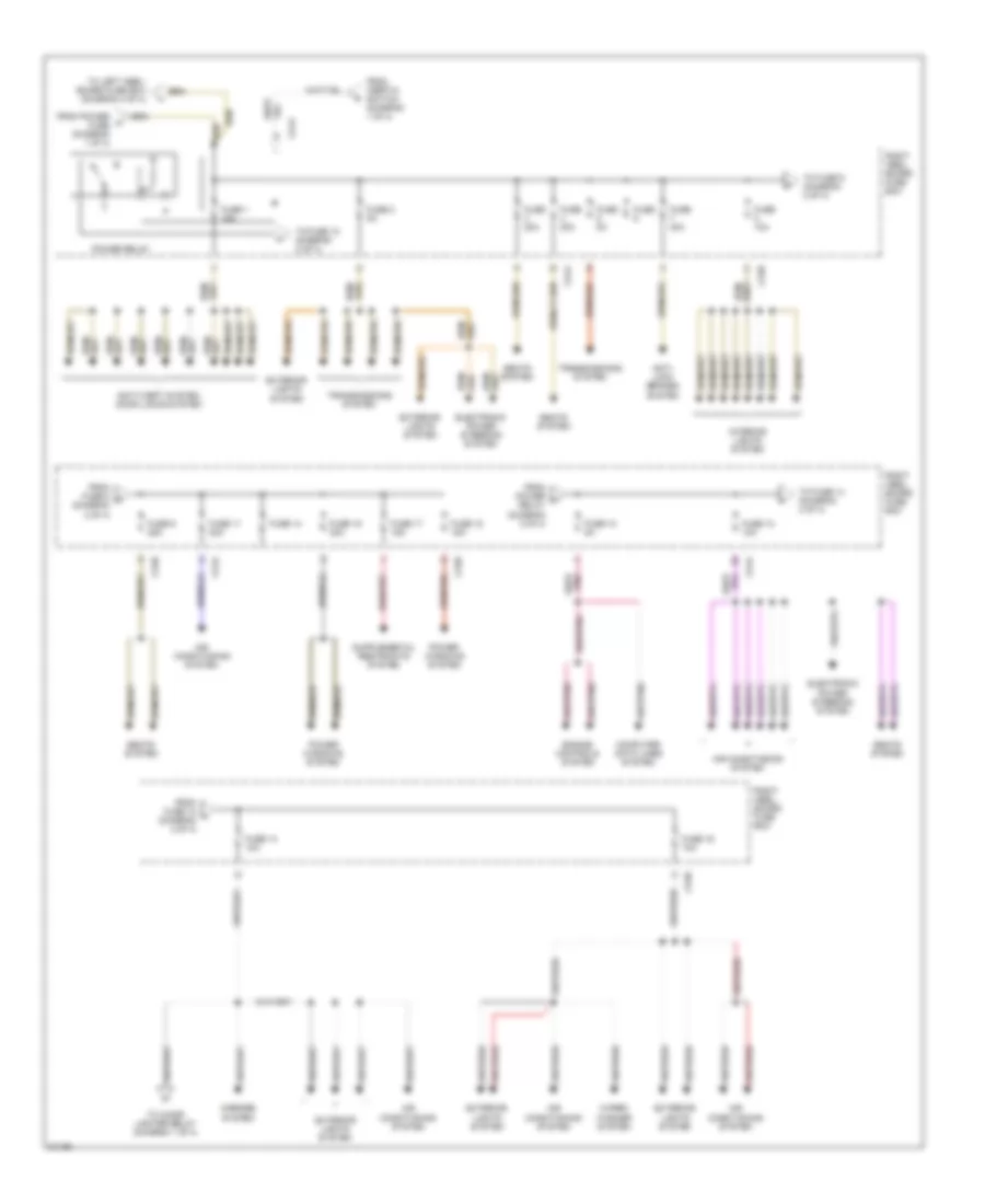
Power Distribution Wiring Diagram (2 of 4) for Jaguar XJ6 Vanden Plas 1995
List of elements for Power Distribution Wiring Diagram (2 of 4) for Jaguar XJ6 Vanden Plas 1995:
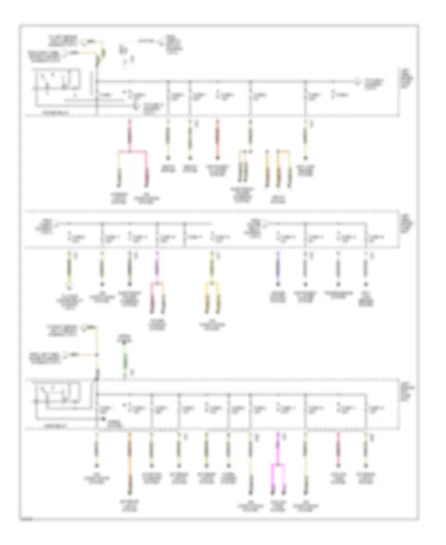
Power Distribution Wiring Diagram (3 of 4) for Jaguar XJ6 Vanden Plas 1995
List of elements for Power Distribution Wiring Diagram (3 of 4) for Jaguar XJ6 Vanden Plas 1995:
Power Distribution Wiring Diagram (4 of 4) for Jaguar XJ6 Vanden Plas 1995
List of elements for Power Distribution Wiring Diagram (4 of 4) for Jaguar XJ6 Vanden Plas 1995: