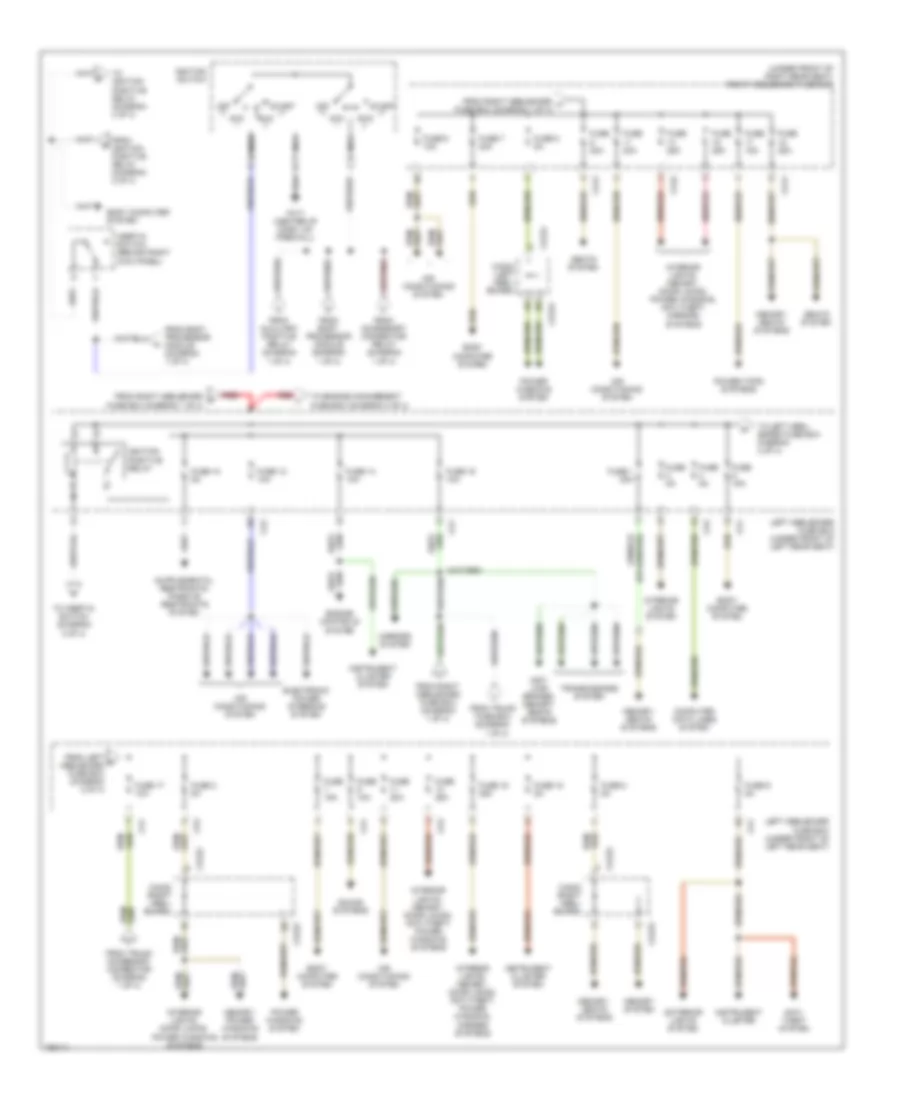
POWER DISTRIBUTION
Power Distribution Wiring Diagram (1 of 4) for Jaguar XJR 2003

List of elements for Power Distribution Wiring Diagram (1 of 4) for Jaguar XJR 2003:
- (diagram 1 of 4)
- (in trunk, next to battery) high power protection module
- (not used)
- (right rear wheelwell) bt65
- (right side of trans tunnel) ca47
- (right side of trunk) trunk fuse box
- Accessory connector relay (relay 6)
- After dealer prep
- Air conditioning system
- Auxiliary positive relay
- Battery
- Before dealer prep
- Body computer system
- Body processor module (behind glove box)
- Bt10
- Bt11
- Bt12
- Bt13
- Bt21 (right rear side of trunk)
- Bt25
- Bt37
- Ca37 (right "a" pillar)
- Ca41
- Ca42
- Ca71
- Ca74
- Ca75
- Ca76
- Computer data lines system
- Defogger system
- Door locks system
- Engine controls system
- Exterior lights system
- Fc15
- From high power protection module c
- From trunk fuse box (diagram 1 of 4)
- From v trunk fuse box (diagram 1 0f 4)
- Front cigar lighter
- Fuel pump relay 1 (relay 4)
- Fuel pump relay 2 (relay 1) (super charged engine only)
- Fuse
- Fuse (not used)
- Fuse 1 20a
- Fuse 10a
- Fuse 15 20a
- Fuse 2 15a
- Fuse 25a
- Fuse 3 15a
- Fuse 4 10a
- Fuse 5 25a
- Fuse 5 5a
- Fuse 5a
- Fuse 7 20a
- Heated backlight relay (relay 2)
- Interior lights system
- Interior lights, navigation, cellular telephone systems
- Mirrors system
- Output
- Passenger compartment accessory connector (right kick panel)
- Power fuse 250a
- Power fuse 500a
- Rear cigar lighter
- Red
- Right heelboard fuse box (under front of right rear seat)
- Right heelboard fuse box (under front of right seat)
- Seats system
- Seats, memory systems
- Side marker & number plate relay (relay 3)
- Sound systems, warning systems
- Starting/ charging system
- Stop- lamp relay (relay 5)
- To ignition switch (diagram 2 of 4)
- To left heelboard fuse box (diagram 2 of 4)
- To right heelboard fuse box (diagram 1 of 4)
- To right heelboard fuse box (diagram 2 of 4)
- To trunk accessory connector (diagram 1 of 4)
- To trunk fuse box (diagram 1 of 4)
- To trunk fuse box (diagram 4 of 4)
- Transit isolation device (in trunk, next to battery)
- Trunk accessory connector (adjacent to battery)
- Trunk fuse box (right side of trunk)
- Wake-up grd
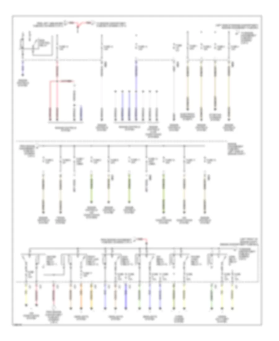
Power Distribution Wiring Diagram (2 of 4) for Jaguar XJR 2003
List of elements for Power Distribution Wiring Diagram (2 of 4) for Jaguar XJR 2003:
- (under front of right rear seat) right heelboard fuse box
- Acc
- Air conditioning system
- Anti- lock brakes, memory, seats systems
- Anti- theft system
- Body computer system
- Ca1
- Ca2
- Ca222
- Ca222 (right heel- board)
- Ca223
- Ca223 (right heel- board)
- Ca224
- Ca224 (left heel- board)
- Ca41
- Ca42
- Computer data lines system
- Electronic power steering system
- Engine controls system
- Exterior lights system
- Fc17 (center of dash, on firewall)
- From accessory connector relay (diagram 1 of 4)
- From auxiliary positive relay (diagram 1 of 4)
- From body processor module (diagram 1 of 4)
- From ignition positive relay (diagram 2 of 4)
- From left n heelboard fuse box (diagram 2 of 4)
- From right heelboard f fuse box (diagram 1 of 4)
- From right heelboard fuse box (diagram 1 of 4)
- From right heelboard h fuse box (diagram 1 of 4)
- From trunk
- From trunk accessory connector (diagram 1 of 4)
- Fuse 1 20a
- Fuse 10 5a
- Fuse 10a
- Fuse 12 10a
- Fuse 14 10a
- Fuse 15 25a
- Fuse 15a
- Fuse 16 10a
- Fuse 17 10a
- Fuse 18 5a
- Fuse 2 5a
- Fuse 20a
- Fuse 25a
- Fuse 5a
- Fuse 6 10a
- Fuse 6 5a
- Fuse 7 20a
- Fuse 8 5a
- Fuse box (diagram 1 of 4)
- Ignition positive relay
- Ignition switch
- Iii
- Inertia switch (behind right kick panel)
- Instrument cluster
- Instrument cluster system
- Interior lights system
- Interior lights, door locks, power windows systems
- Interior lights, memory, door locks, anti-theft, power windows systems
- Interior lights, memory, door locks, anti-theft, power windows, mirrors systems
- Interior lights, memory, door locks, power windows, anti-theft, mirrors systems
- Left heelboard fuse box (under front of left rear seat)
- Memory system
- Memory, power windows systems
- Memory, seats systems
- Mirrors system
- Nca
- Off
- Power tops systems
- Power windows system
- Red
- Run
- Seats system
- Sound systems
- Start
- To engine management fuse box (diagram 3 of 4)
- To ignition positive relay (diagram 4 of 4)
- To inertia switch (diagram 2 of 4)
- To left heel- board fuse box diagram 2 of 4)
- Transmissions system
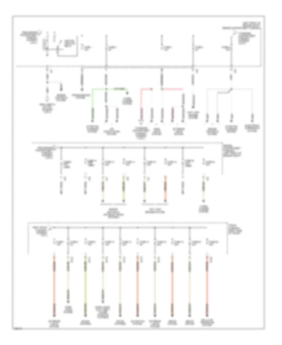
Power Distribution Wiring Diagram (3 of 4) for Jaguar XJR 2003
List of elements for Power Distribution Wiring Diagram (3 of 4) for Jaguar XJR 2003:
- (left front of engine compt) engine compartment fuse box
- (left side of engine compartment) engine management fuse box
- (not used)
- Air conditioning system
- Dip beam relay (relay 5)
- Electronic suspension sysetm
- Em19
- Em20
- Ems control relay
- Engine controls & air conditioning systems
- Engine controls system
- Engine controls, air conditioning systems
- Engine management fuse box (left side of engine compt)
- From engine compartment fuse box (diagram 4 of 4)
- From engine management p fuse box (diagram 3 of 4)
- From engine q management fuse box (diagram 3 of 4)
- From left heelboard j fuse box (diagram 2 of 4)
- Front fog lamp relay (relay 2)
- Fuse 1 20a
- Fuse 10 10a
- Fuse 10a
- Fuse 11 30a
- Fuse 12 10a
- Fuse 13 (not used)
- Fuse 14 10a
- Fuse 15 30a
- Fuse 17 15a
- Fuse 17 30a
- Fuse 18 10a
- Fuse 2 15a
- Fuse 3 25a
- Fuse 30a
- Fuse 4 10a
- Fuse 5 10a
- Fuse 5a
- Fuse 6 5a
- Fuse 7 (not used)
- Fuse 8 10a
- Fuse 9 30a
- Headlights system
- Heater pump relay (relay 1)
- Horn relay (relay 6)
- Horns/ anti-theft system
- Lf5
- Lf6
- Lf7
- Lf8
- Main beam relay (relay 3)
- Power- wash relay (relay 4)
- Red
- Starting/ charging system
- To engine compartment fuse box (diagram 3 of 4)
- To engine compartment fuse box (diagram 4 of 4)
- To engine management fuse box (diagram 3 of 4)
- Trans- missions system
- Wiper/ washer system
Power Distribution Wiring Diagram (4 of 4) for Jaguar XJR 2003
List of elements for Power Distribution Wiring Diagram (4 of 4) for Jaguar XJR 2003:
- (left front of engine compt) engine compartment fuse box
- (not used)
- Air conditioning system
- Anti-lock brakes system
- Bt10
- Bt11
- Bt12
- Bt13
- Cellular telephone system
- Door locks system
- Door locks, anit-theft, power windows systems
- Electronic suspension system
- Engine compartment fuse box (left front of engine compt)
- Engine controls system
- Engine controls, air conditioning systems
- Exterior lights system
- From engine r compartment fuse box (diagram 3 of 4)
- From engine t compartment fuse box (diagram 4 of 4)
- From inertia switch (diagram 2 of 4)
- From trunk w fuse box (diagram 1 of 4)
- Fuse 1 10a
- Fuse 10 (not used)
- Fuse 10 10a
- Fuse 12 30a
- Fuse 14 30a
- Fuse 14 5a
- Fuse 16 20a
- Fuse 16 30a
- Fuse 18 20a
- Fuse 18 30a
- Fuse 2 5a
- Fuse 20 (not used)
- Fuse 20 20a
- Fuse 22 20a
- Fuse 22 30a
- Fuse 3 10a
- Fuse 4 5a
- Fuse 5 10a
- Fuse 9 (not used)
- Fuse 9 10a
- Head lights system
- Ignition positive relay
- Lf5
- Lf6
- Lf7
- Lf8
- Navigation system
- Seats system
- Sound systems
- Starting/ charging system
- To engine compartment fuse box (diagram 3 of 4)
- To engine compartment fuse box (diagram 4 of 4)
- Transmissions system
- Trunk fuse box (right side of trunk)
- Wiper/ washer system