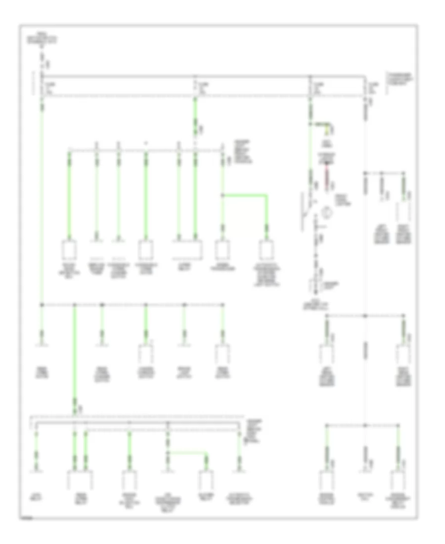
POWER DISTRIBUTION
Power Distribution Wiring Diagram (1 of 3) for Land Rover Defender 90 1997

List of elements for Power Distribution Wiring Diagram (1 of 3) for Land Rover Defender 90 1997:
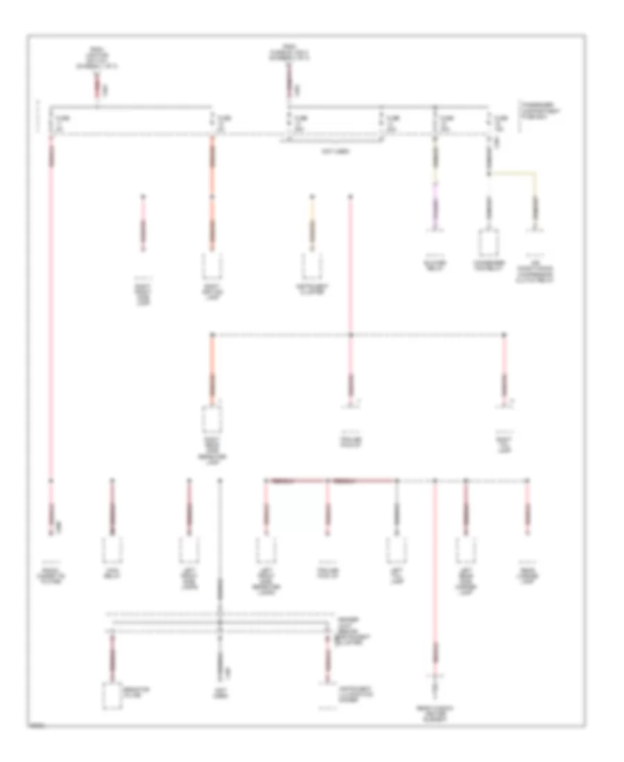
Power Distribution Wiring Diagram (2 of 3) for Land Rover Defender 90 1997
List of elements for Power Distribution Wiring Diagram (2 of 3) for Land Rover Defender 90 1997:
Power Distribution Wiring Diagram (3 of 3) for Land Rover Defender 90 1997
List of elements for Power Distribution Wiring Diagram (3 of 3) for Land Rover Defender 90 1997: