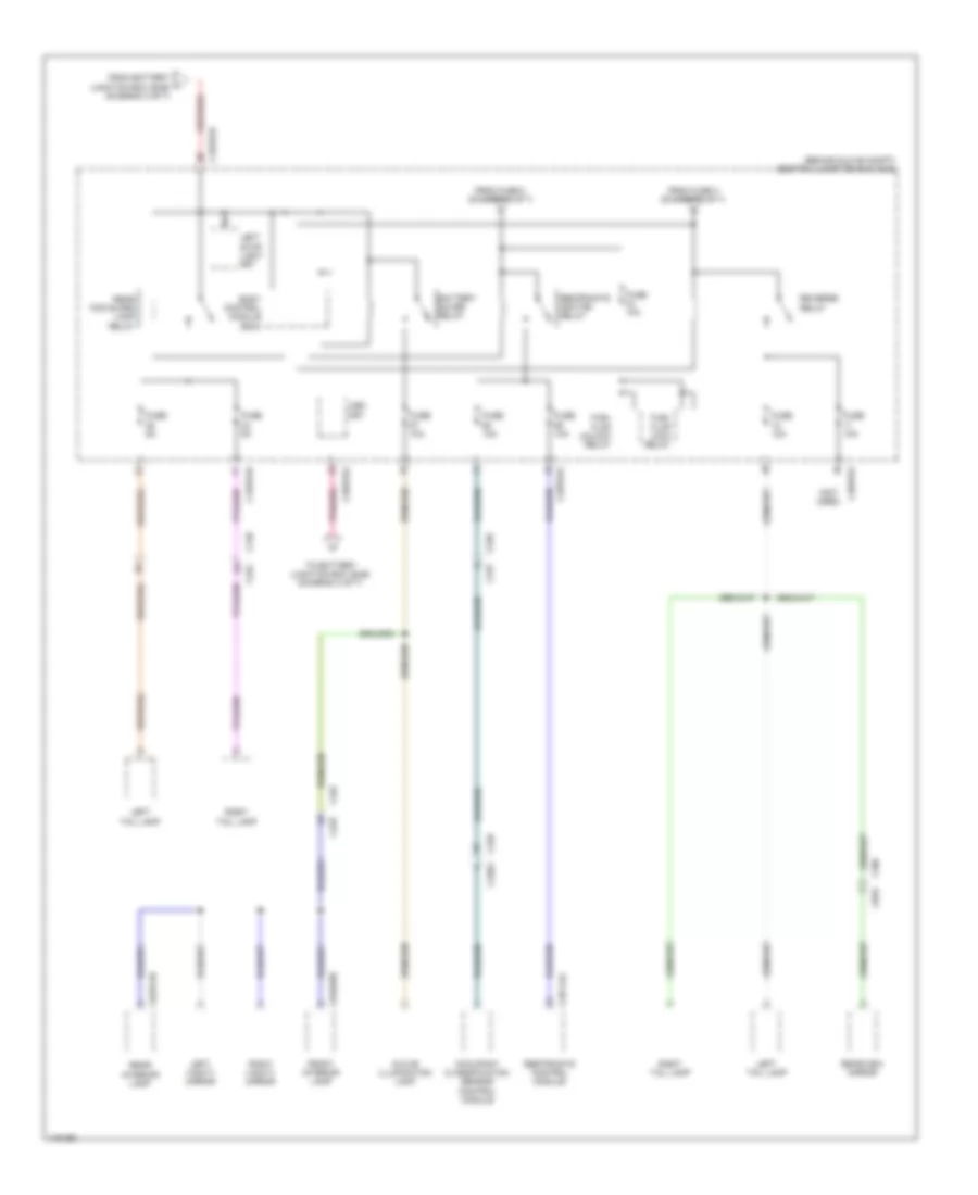
POWER DISTRIBUTION
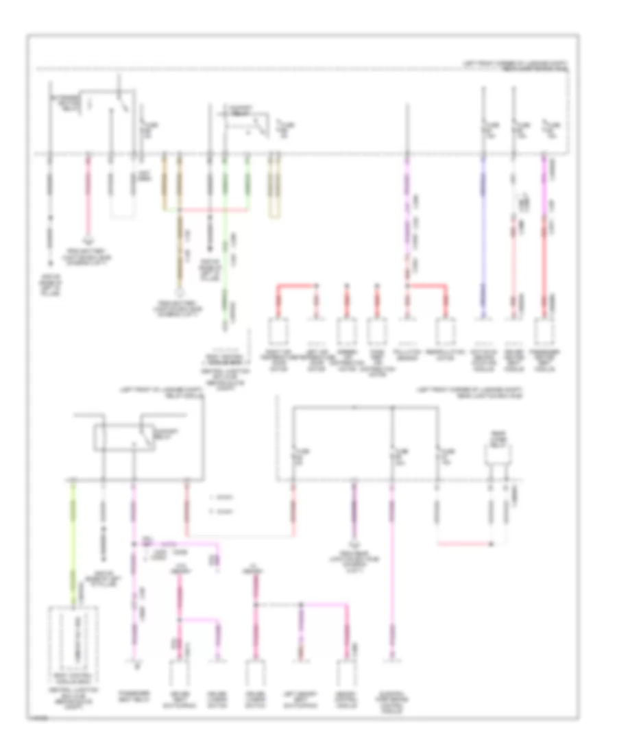
Power Distribution Wiring Diagram (1 of 7) for Land Rover Discovery 2 HSE Lux 2014

List of elements for Power Distribution Wiring Diagram (1 of 7) for Land Rover Discovery 2 HSE Lux 2014:
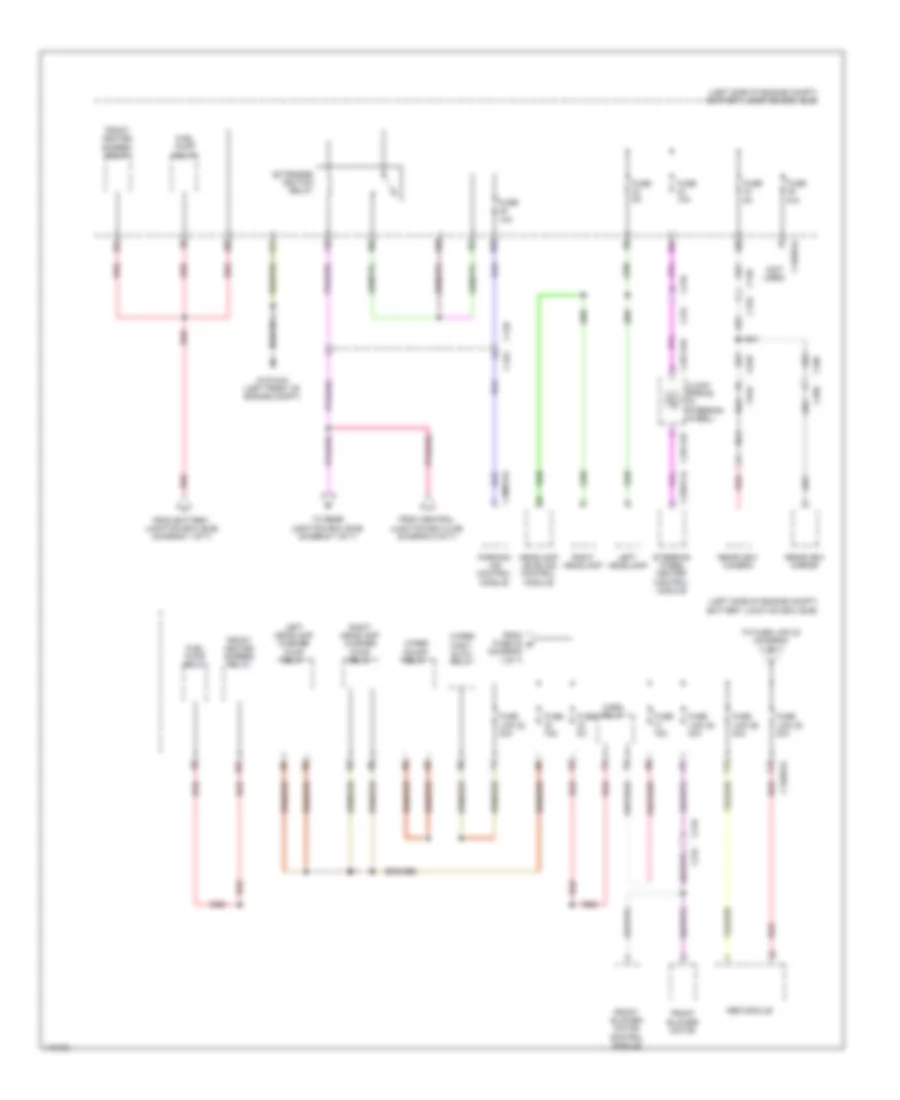
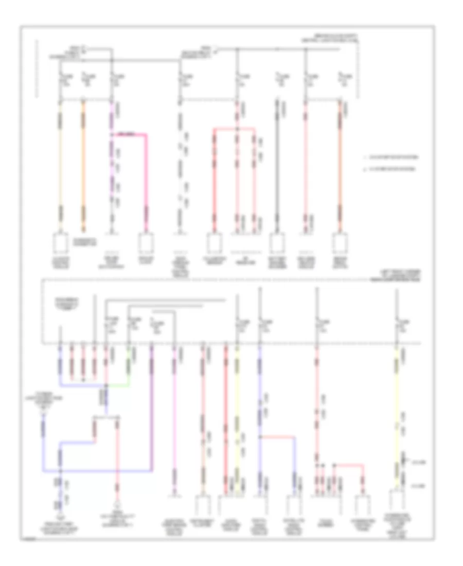
Power Distribution Wiring Diagram (2 of 7) for Land Rover Discovery 2 HSE Lux 2014
List of elements for Power Distribution Wiring Diagram (2 of 7) for Land Rover Discovery 2 HSE Lux 2014:
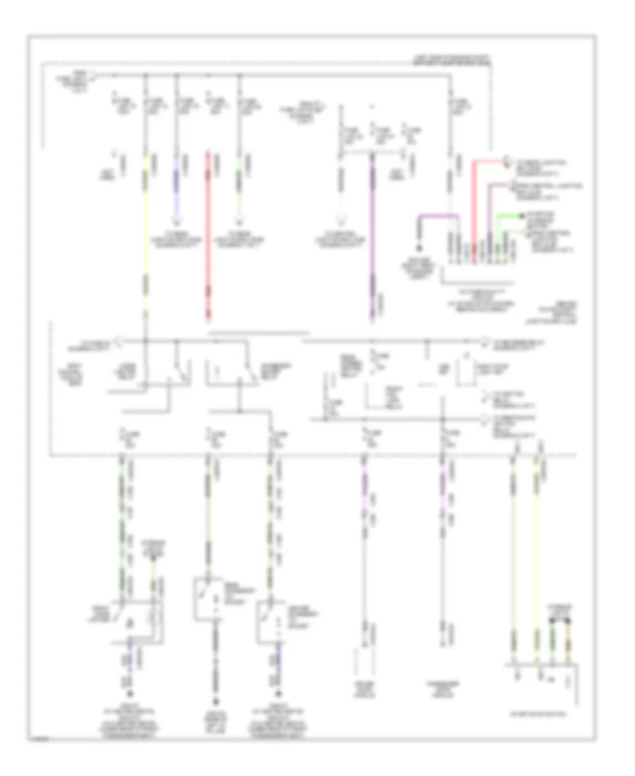
Power Distribution Wiring Diagram (3 of 7) for Land Rover Discovery 2 HSE Lux 2014
List of elements for Power Distribution Wiring Diagram (3 of 7) for Land Rover Discovery 2 HSE Lux 2014:
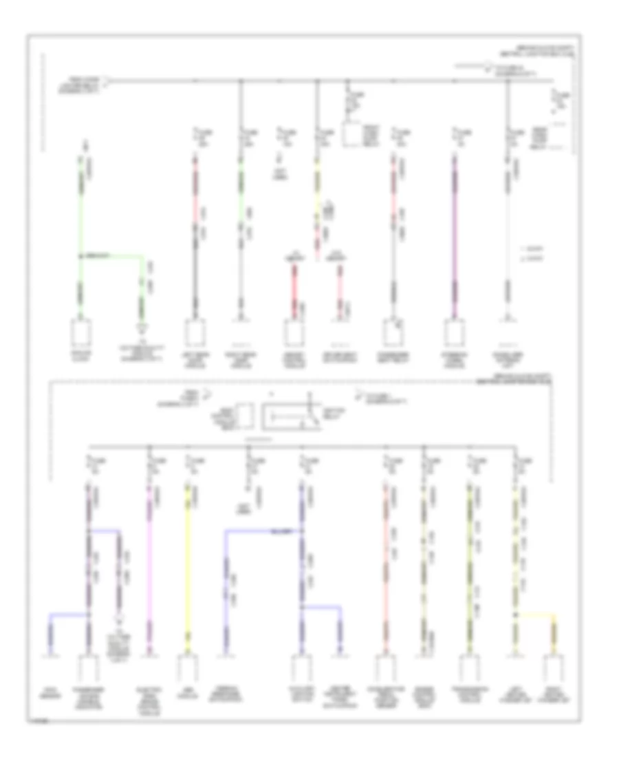
Power Distribution Wiring Diagram (4 of 7) for Land Rover Discovery 2 HSE Lux 2014
List of elements for Power Distribution Wiring Diagram (4 of 7) for Land Rover Discovery 2 HSE Lux 2014:
Power Distribution Wiring Diagram (5 of 7) for Land Rover Discovery 2 HSE Lux 2014
List of elements for Power Distribution Wiring Diagram (5 of 7) for Land Rover Discovery 2 HSE Lux 2014:
Power Distribution Wiring Diagram (6 of 7) for Land Rover Discovery 2 HSE Lux 2014
List of elements for Power Distribution Wiring Diagram (6 of 7) for Land Rover Discovery 2 HSE Lux 2014:
Power Distribution Wiring Diagram (7 of 7) for Land Rover Discovery 2 HSE Lux 2014
List of elements for Power Distribution Wiring Diagram (7 of 7) for Land Rover Discovery 2 HSE Lux 2014: