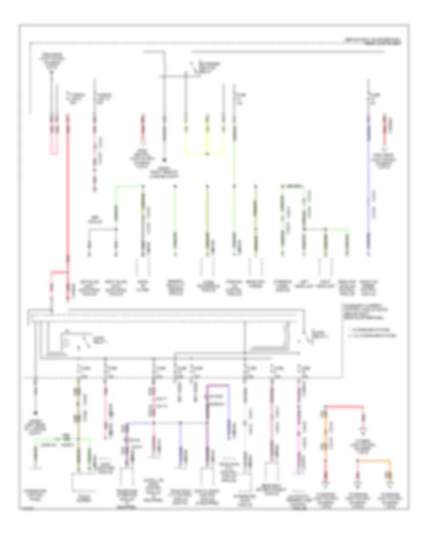
POWER DISTRIBUTION
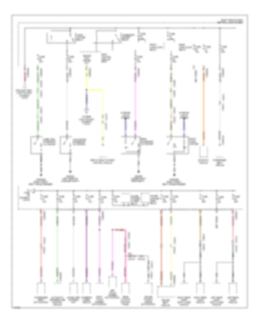
Power Distribution Wiring Diagram (1 of 9) for Land Rover Range Rover Sport Autobiography 2014

List of elements for Power Distribution Wiring Diagram (1 of 9) for Land Rover Range Rover Sport Autobiography 2014:
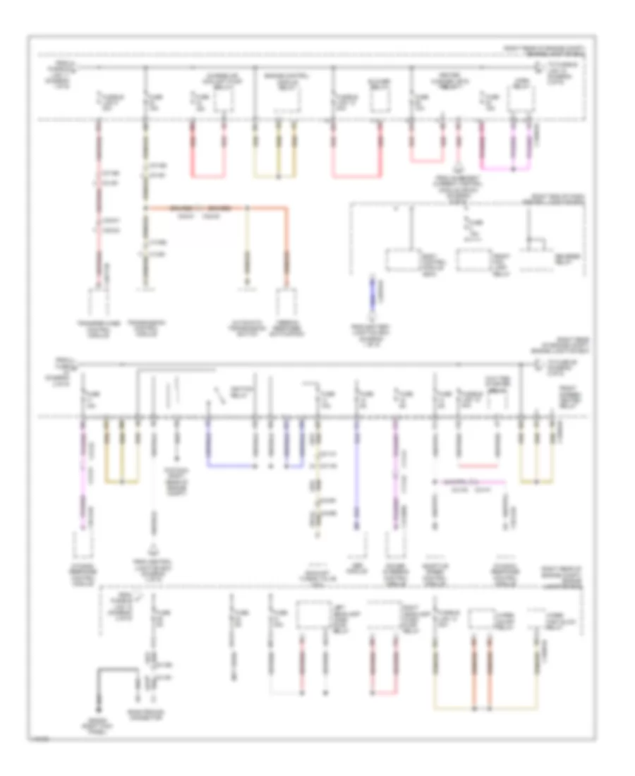
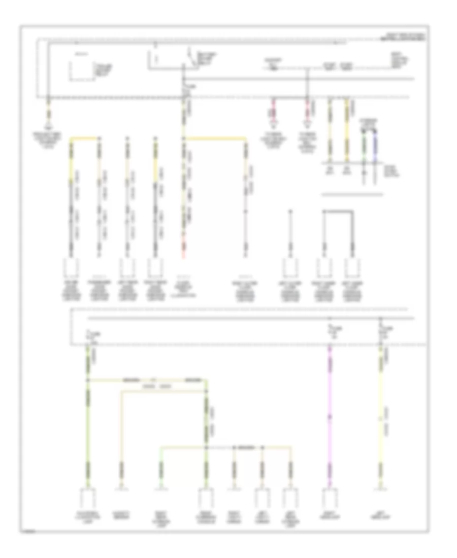
Power Distribution Wiring Diagram (2 of 9) for Land Rover Range Rover Sport Autobiography 2014
List of elements for Power Distribution Wiring Diagram (2 of 9) for Land Rover Range Rover Sport Autobiography 2014:
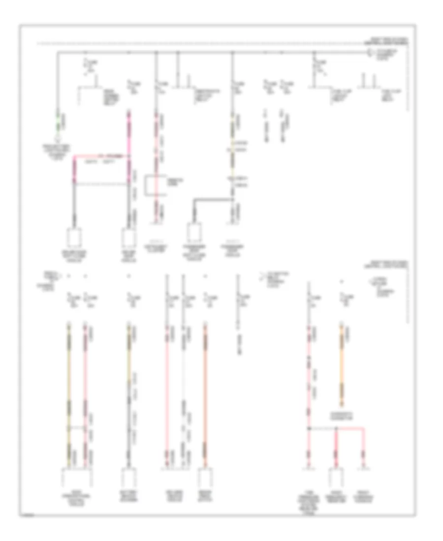
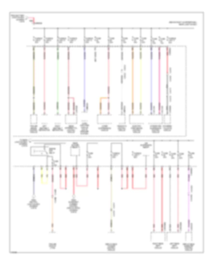
Power Distribution Wiring Diagram (3 of 9) for Land Rover Range Rover Sport Autobiography 2014
List of elements for Power Distribution Wiring Diagram (3 of 9) for Land Rover Range Rover Sport Autobiography 2014:
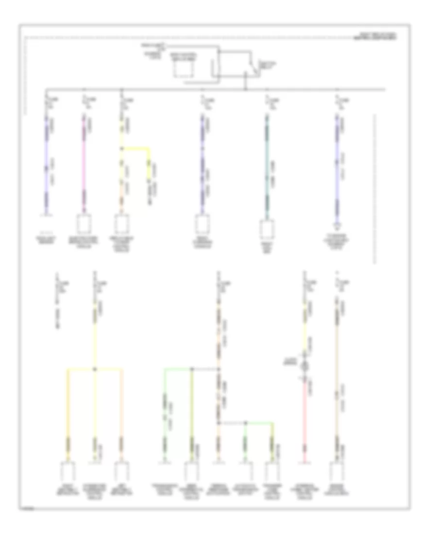
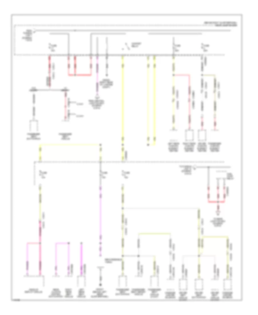
Power Distribution Wiring Diagram (4 of 9) for Land Rover Range Rover Sport Autobiography 2014
List of elements for Power Distribution Wiring Diagram (4 of 9) for Land Rover Range Rover Sport Autobiography 2014:
Power Distribution Wiring Diagram (5 of 9) for Land Rover Range Rover Sport Autobiography 2014
List of elements for Power Distribution Wiring Diagram (5 of 9) for Land Rover Range Rover Sport Autobiography 2014:
Power Distribution Wiring Diagram (6 of 9) for Land Rover Range Rover Sport Autobiography 2014
List of elements for Power Distribution Wiring Diagram (6 of 9) for Land Rover Range Rover Sport Autobiography 2014:
Power Distribution Wiring Diagram (7 of 9) for Land Rover Range Rover Sport Autobiography 2014
List of elements for Power Distribution Wiring Diagram (7 of 9) for Land Rover Range Rover Sport Autobiography 2014:
Power Distribution Wiring Diagram (8 of 9) for Land Rover Range Rover Sport Autobiography 2014
List of elements for Power Distribution Wiring Diagram (8 of 9) for Land Rover Range Rover Sport Autobiography 2014:
Power Distribution Wiring Diagram (9 of 9) for Land Rover Range Rover Sport Autobiography 2014
List of elements for Power Distribution Wiring Diagram (9 of 9) for Land Rover Range Rover Sport Autobiography 2014: