POWER DISTRIBUTION
Power Distribution Wiring Diagram (1 of 2) for Lexus GS 400 1998

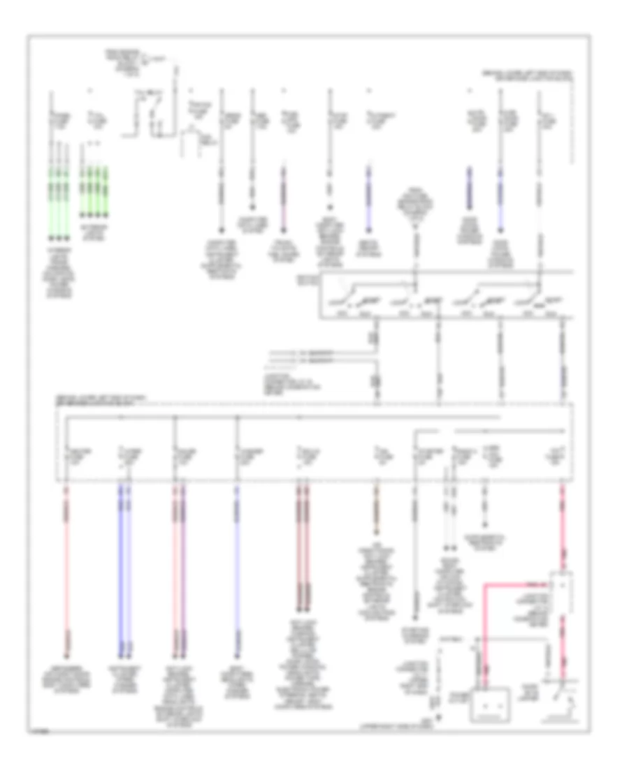
List of elements for Power Distribution Wiring Diagram (1 of 2) for Lexus GS 400 1998:
- (behind lower right end of dash) passenger side junction block
- (canada)
- (on left side of engine compt, front of strut tower) engine room relay block 3
- (on right side of engine compt, behind strut tower) engine room relay block 1
- (usa)
- Abs 1 fuse 60a
- Abs 2 fuse 40a
- Air conditioning, headlights, memory systems
- Alt fuse 120a
- Alt-s fuse 5a
- Am2 fuse 15a
- Anti-lock brakes system
- Battery
- Body computer, door locks, power window systems
- Body computer, sound, instrument cluster, interior lights, trunk, tailgate, fuel doors, body computer, door locks systems
- Cds fan fuse 30a
- Cellular phones system
- Cooling fans system
- Defog fuse 30a
- Defogger system
- Defogger, body computer, engine controls, air conditioning systems
- Dimmer drl 2 relay
- Dome fuse 10a
- Drl 1 fuse (canada) 30a
- Drl 2 fuse 30a
- Ecu-b1 fuse 20a
- Ecu-b2 fuse 5a
- Efi fuse 25a
- Eng main relay
- Engine controls system
- Engine controls, computer data lines systems
- Etcs fuse 15a
- Exterior lights system
- Fan main fuse 50a
- From a engine room relay block 1 (diagram 1 of 2)
- H-lp cln fuse 30a
- H10
- H12
- Head- light relay
- Headlights system
- Heater fuse 50a
- Horn fuse 10a
- Horns, body computer systems
- Ig relay
- Instrument cluster, body computer, power windows, door locks, memory systems
- Left high beam head- light
- Left lower head fuse (canada) 15a
- Left upper head fuse (usa) 10a
- Left upper head fuse 15a
- Main fuse 40a
- Mir htr fuse 10a
- Mir relay
- Mpx-b fuse 10a
- Navigation system
- P fr door fuse 20a
- P p/ seat fuse 30a
- P rr door fuse 20a
- Power tops system
- Radio 1 fuse 20a
- Rdi fan fuse 30a
- Red
- Right high beam head- light
- Right lower head fuse (canada) 15a
- Right upper head fuse (usa) 10a
- Right upper head fuse 15a
- S/roof fuse 25a
- Seat htr fuse 20a
- Seats system
- Sound systems
- Starting/ charging system
- Tel fuse 15a
- To driver side junction block (diagram 2 of 2)
- To engine room relay block 1 (diagram 1 of 2)
- To ignition switch (diagram 2 of 2)
- Turn/ hazard fuse 10a
- Tv fuse 15a
- Wiper/ washer system
Power Distribution Wiring Diagram (2 of 2) for Lexus GS 400 1998
List of elements for Power Distribution Wiring Diagram (2 of 2) for Lexus GS 400 1998:
- (behind lower left end of dash) driver side junction block
- Acc
- Am 1 fuse 40a
- Anti-lock brakes, instrument cluster, computer data lines, headlights, engine controls, exterior lights shift interlock systems
- Anti-lock brakes, warning, instrument cluster, cellular phones, door locks, power windows, headlights, power tops, mirrors, electronic power steering, seats, memory, body computers systems
- Body computer, anti-lock brakes, engine controls, exterior lights systems
- Body computers, headlights, wiper/ washer systems
- Cicar- ette lighter
- Cig fuse 15a
- Computer data lines system
- D fr door fuse 20a
- D p/seat fuse 30a
- D rr door fuse 20a
- Defoggers, air conditioning engine controls, body computers systems
- Door locks, power windows systems
- E11
- Ecu-ig fuse 15a
- Exterior lights system
- F10
- Fog relay
- Fr fog fuse 15a
- From am2 fuse, engine room relay block (diagram 1 of 2)
- From engine room relay block 1 (diagram 1 of 2)
- Fuel opn fuse 10a
- G201 (upper right side of dash)
- Gauge fuse 10a
- H10
- H12
- Heater fuse 10a
- Ign fuse 5a
- Ignition switch
- Instrument cluster, wiper/ washer systems
- Interior lights, trans- missions, navigation, door locks, power windows systems
- Junction connector j/c 12 (behind combination meter)
- Junction connector j/c 15 (behind combination meter)
- Junction connector j/c 17 (upper right end of dash)
- Lock
- Obd fuse 7.5a
- Panel fuse 7.5a
- Pnk
- Power outlet
- Radio 2 fuse 15a
- Run
- Seats, memory systems
- Sound, body computer, air con- ditioning, instrument cluster, navigation, shift interlock systems
- Srs acc fuse 15a
- Srs-b fuse 5a
- Start
- Starter fuse 5a
- Starting/ charging system
- Stop fuse 15a
- Tail fuse 10a
- Tail relay
- Trunk, tailgate, fuel doors system
- Washer fuse 20a
- Wiper fuse 25a