POWER DISTRIBUTION
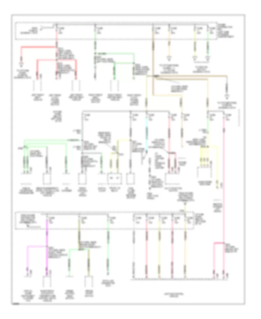
Power Distribution Wiring Diagram (1 of 5) for Lincoln Continental 1997

List of elements for Power Distribution Wiring Diagram (1 of 5) for Lincoln Continental 1997:
- (eng compt harn, in anti-lock brake control module breakout) s117
- (engine compt harn. front center of eng compt) s199
- (i/p harn, near left kick panel) s226
- (rear body harn, center front of trunk) s434
- Abs evac and fill connector
- Air bag diagnostic monitor
- Air injection reaction (air) management electric solenoid
- Air injection reaction (air) management relay
- Anti-lock brake control module
- Battery
- Blower motor relay
- C277
- C522
- C524
- C601
- C711
- C811
- Compressor relay
- Daytime running lamps (drl) module
- Dual auxiliary box
- From fuse 15 (diagram 1 of 5)
- From fuse 8 (diagram 1 of 5)
- Fuse 10a
- Fuse 15aa
- Fuse 20a
- Fuse 30a
- Fuse 40a
- Fuse 60a
- Generator/ voltage regulator
- Hi beam relay
- High speed cooling fan relay
- Horn relay
- I/p fuse panel (below left side of i/p)
- Left front door module
- Left rear window switch
- Low speed cooling fan relay
- Mega fuse 175a
- Pcm power relay
- Pnk
- Power distribution box (left side of engine compartment)
- Powertrain control module (pcm)
- Rear window defrost control
- Red
- Right front window switch
- Right rear window switch
- S133 (engine compt harn. near top front of left front fender)
- Starter motor assembly
- To fuse 13 (diagram 2 of 5)
- To fuse 17 (diagram 1 of 5)
- To fuse 9 (diagram 1 of 5)
- Vehicle dynamic module (vdm)
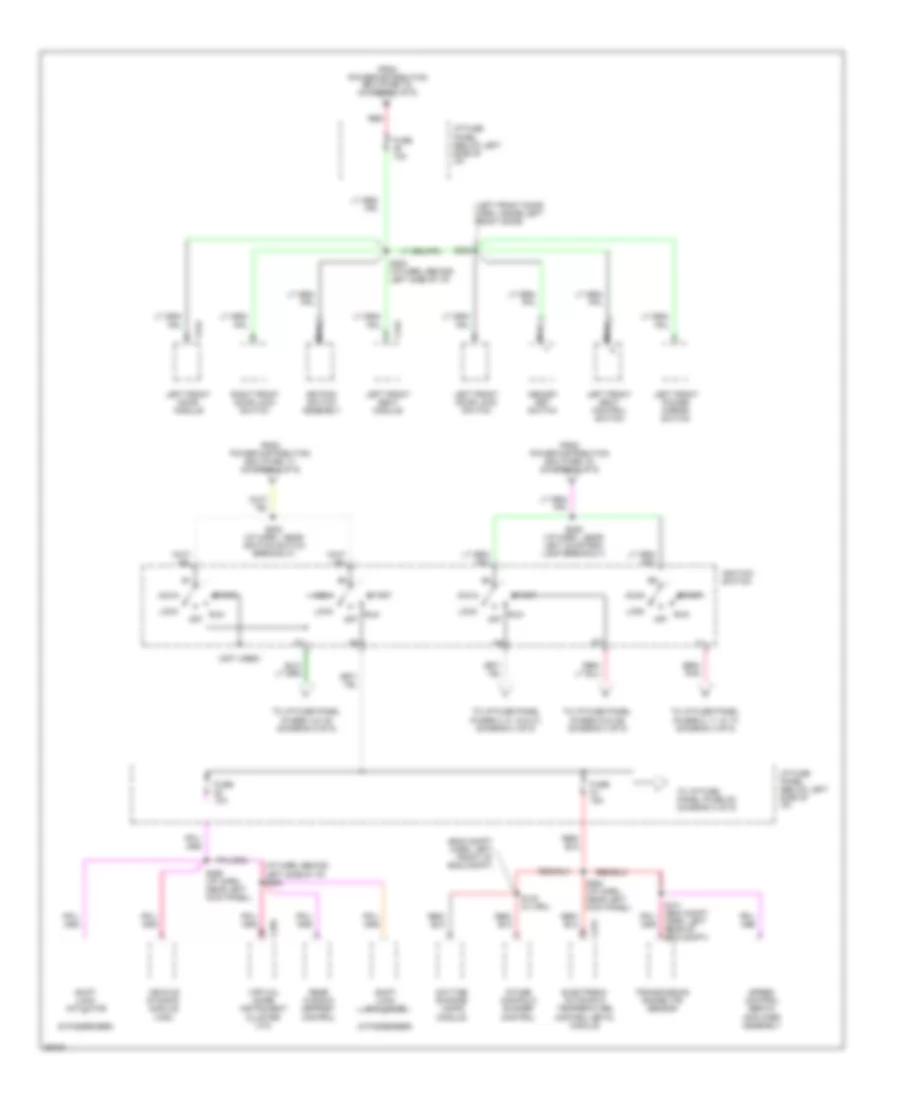
Power Distribution Wiring Diagram (2 of 5) for Lincoln Continental 1997
List of elements for Power Distribution Wiring Diagram (2 of 5) for Lincoln Continental 1997:
- (body harn, near subwoofer amp breakout) s406
- (i/p harn, near brake on/off switch breakout) s251
- (i/p harn, near i/p fuse panel breakout)
- (i/p harn, near left kick panel)
- (i/p harn, near multi- function sw breakout)
- (rear body harn, near trunk lid relay breakout)
- Brake on/off switch
- Breakout)
- C207
- C208
- C231
- C256
- C268
- C269
- C275
- C348
- C362
- C401
- C448
- C456
- C470
- Cd changer
- Data link connector (dlc)
- Digital clock
- Electronic automatic temperature control (eatc) module
- From fuse 22 (diagram 1 of 5)
- From power distribution box (fuse 5) (diagram 2 of 5)
- From power distribution box (fuse 6) (diagram 2 of 5)
- Front control unit (radio)
- Fuel filler door release switch
- Fuse 10a
- Fuse 15a
- Fuse 20a
- Fuse 30a
- Fuse 40a
- Fuse 60a
- G200 (left kick panel)
- I/p cigar lighter or console cigar lighter
- I/p fuse panel (below left side of i/p)
- Left front 2 way power lumbar switch
- Left front heated seat module
- Left front seat module
- Lighting control module
- Mobile telephone transceiver
- Multi-function switch
- Nca
- Pnk
- Power distribution box (left side of engine compartment)
- Power point
- Red
- Remote chassis unit (radio)
- Remote emergency satellite cellular unit (rescu) module
- Right front 2 way power lumbar switch
- Right front heated seat module
- Right front seat control switch
- S200
- S230 (i/p harn, near left kick panel)
- S238 (i/p harn, behind left side of i/p)
- S239
- S241 (i/p harn, in i/p fuse panel breakout)
- S252 (i/p harn, behind left side of i/p)
- S253 (i/p harn, near elect temp control module breakout)
- S259 (i/p harn, near digital clock breakout)
- S313 (body harn, left side of vehicle, near driver's seat)
- S316 (body harn, near power lumbar switch breakout)
- S322 (body harn, near power lumbar sw breakout)
- S369
- S441
- Speed control deac switch
- Subwoofer amplifier
- Tan
- Tan/red
- To i/p fuse panel (fuse 26) (diagram 2 of 5)
- To i/p fuse panel (fuse 39) (diagram 3 of 5)
- To i/p fuse panel (fuses 1, 7, 13, 19 & 25) (diagram 2 of 5)
- To ignition switch (diagram 3 of 5)
- Trunk lid relay
- Virtual image instrument cluster (vic)
Power Distribution Wiring Diagram (3 of 5) for Lincoln Continental 1997
List of elements for Power Distribution Wiring Diagram (3 of 5) for Lincoln Continental 1997:
- (5 passenger)
- (6 passenger)
- (eng compt harn, left front of eng compt)
- (i/p harn, behind left side of i/p) s268
- (left front door harn, inside left front door)
- (not used)
- Acc
- C256
- C275
- C342
- C524
- Daytime running lamps module
- Electronic automatic temperature control (eatc) module
- From power distribution box (fuse 11) (diagram 2 of 5)
- From power distribution box (fuse 12) (diagram 2 of 5)
- From power distribution box (fuse 13) (diagram 2 of 5)
- Fuse 10a
- Fuse 15a
- I/p fuse panel (below left side of i/p)
- Ignition switch
- Intake manifold runner control
- Keypad switch assembly
- Left front door lock switch
- Left front door module
- Left front power mirror switch
- Left front seat control switch
- Left front seat module
- Lock
- Memory set switch
- Nca
- Off
- Rear window defrost control
- Red
- Right front door lock switch
- Run
- S140 (w/ drl)
- S141 (eng compt harn, left rear of eng compt)
- S202 (i/p harn , near ignition switch breakout)
- S229 (i/p harn , near left courtesy lamp breakout)
- S254 (i/p harn, behind left side of i/p)
- S264 (i/p harn, near left kick panel)
- S265 (i/p harn, near left kick panel)
- S502
- Shift lock actuator
- Speed control servo/ amplifier assembly
- Start
- To i/p fuse panel (fuse 40) (diagram 4 of 5)
- To i/p fuse panel (fuses 23 & 29) (diagram 4 of 5)
- To i/p fuse panel (fuses 3, 9, 15 & 21) (diagram 4 of 5)
- To i/p fuse panel (fuses 4 & 16) (diagram 5 of 5)
- To i/p fuse panel (fuses 5, 11, & 17) (diagram 4 of 5)
- Transmission range (tr) sensor
- Vehicle dynamic module (vdm)
- Virtual image instrument cluster (vic)
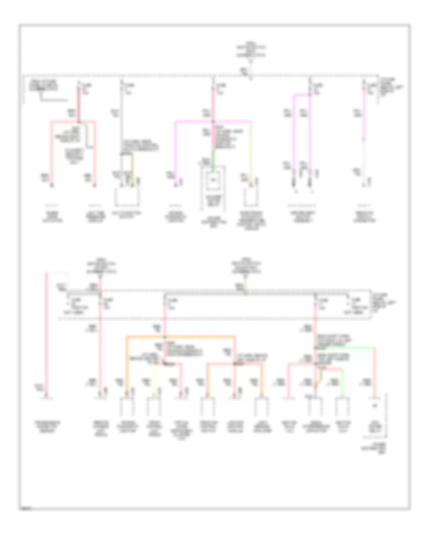
Power Distribution Wiring Diagram (4 of 5) for Lincoln Continental 1997
List of elements for Power Distribution Wiring Diagram (4 of 5) for Lincoln Continental 1997:
- (eng compt harn, top front of left fender apron) s139
- (eng compt harn, top left side of engine) s116
- (i/p harn, behind center of i/p)
- (i/p harn, behind left side of i/p) s247
- (i/p harn, near traction control switch breakout) s220
- (not used)
- Abs evac and fill connector
- Air bag diagnostic monitor
- Blend door actuator
- Blower motor relay
- C146
- C208
- C221
- C222
- C231
- C255
- C268
- C269
- C275
- C276
- C277
- C469
- Electronic automatic temperature control (eatc) module
- From i/p fuse panel (fuse 34) (diagram 3 of 5)
- From igntion switch (run) (diagram 3 of 5)
- From igntion switch (run/start) (diagram 3 of 5)
- From igntion switch (start) (diagram 3 of 5)
- Front control unit (radio)
- Fuse 10a
- Fuse position
- Heated seat switch assembly
- I/p fuse panel (below left side of i/p)
- Ignition coils 1 & 2
- Ignition coils 3 & 4
- Light sensor/ amplifier
- Lighting control module
- Low tire pressure module
- Multi-function switch
- Nca
- Pcm power relay
- Power distribution box
- Radio interference capacitor
- Remote chassis unit (radio)
- S243 (i/p harn, near air bag diagnostic monitor breakout)
- S249
- S257 (i/p harn, behind right side of i/p)
- Traction control switch
- Transmission range (tr) sensor
- Virtual image instrument cluster (vic)
- W/ safety security package only
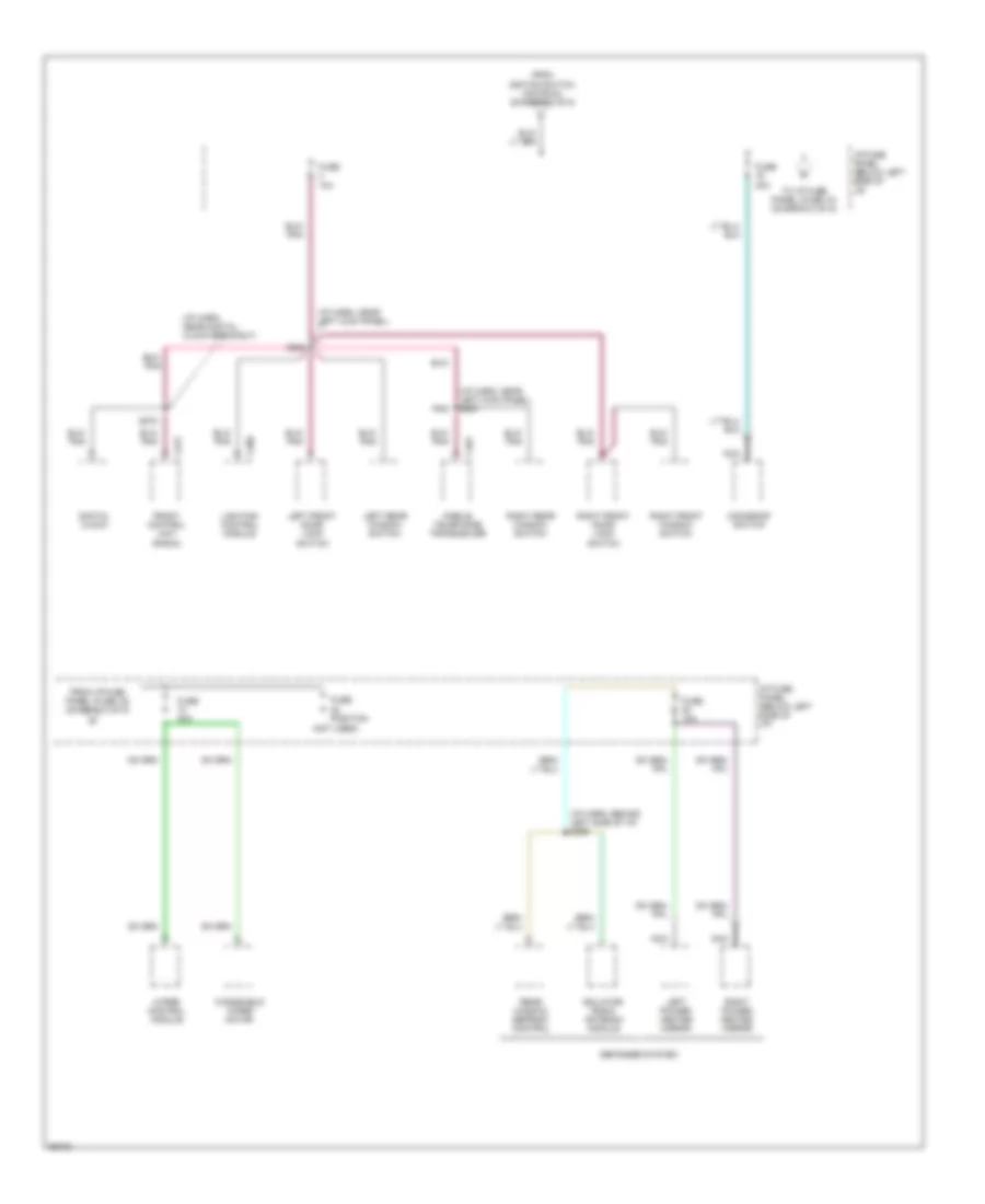
Power Distribution Wiring Diagram (5 of 5) for Lincoln Continental 1997
List of elements for Power Distribution Wiring Diagram (5 of 5) for Lincoln Continental 1997:
- (i/p harn, behind left side of i/p) s269
- (i/p harn, near digital clock breakout)
- (i/p harn, near left kick panel)
- (i/p harn, near left kick panel) s327
- (not used)
- C208
- C231
- C401
- Defogger system
- Digital clock
- From i/p fuse panel (fuse 16) (diagram 5 of 5)
- From igntion switch (acc/run) (diagram 3 of 5)
- Front control unit (radio)
- Fuse 10a
- Fuse 30a
- Fuse position
- I/p fuse panel (below left side of i/p)
- Isolator/ radio antenna module
- Left front door lock switch
- Left power/ heated mirror
- Left rear window switch
- Lighting control module
- Mobile telephone transceiver
- Moonroof switch
- Nca
- Pnk
- Rear window defrost control
- Right front door lock switch
- Right front window switch
- Right power/ heated mirror
- Right rear window switch
- S248
- S272
- To i/p fuse panel (fuse 10) (diagram 5 of 5)
- Windshield wiper motor
- Wiper control module