POWER DISTRIBUTION
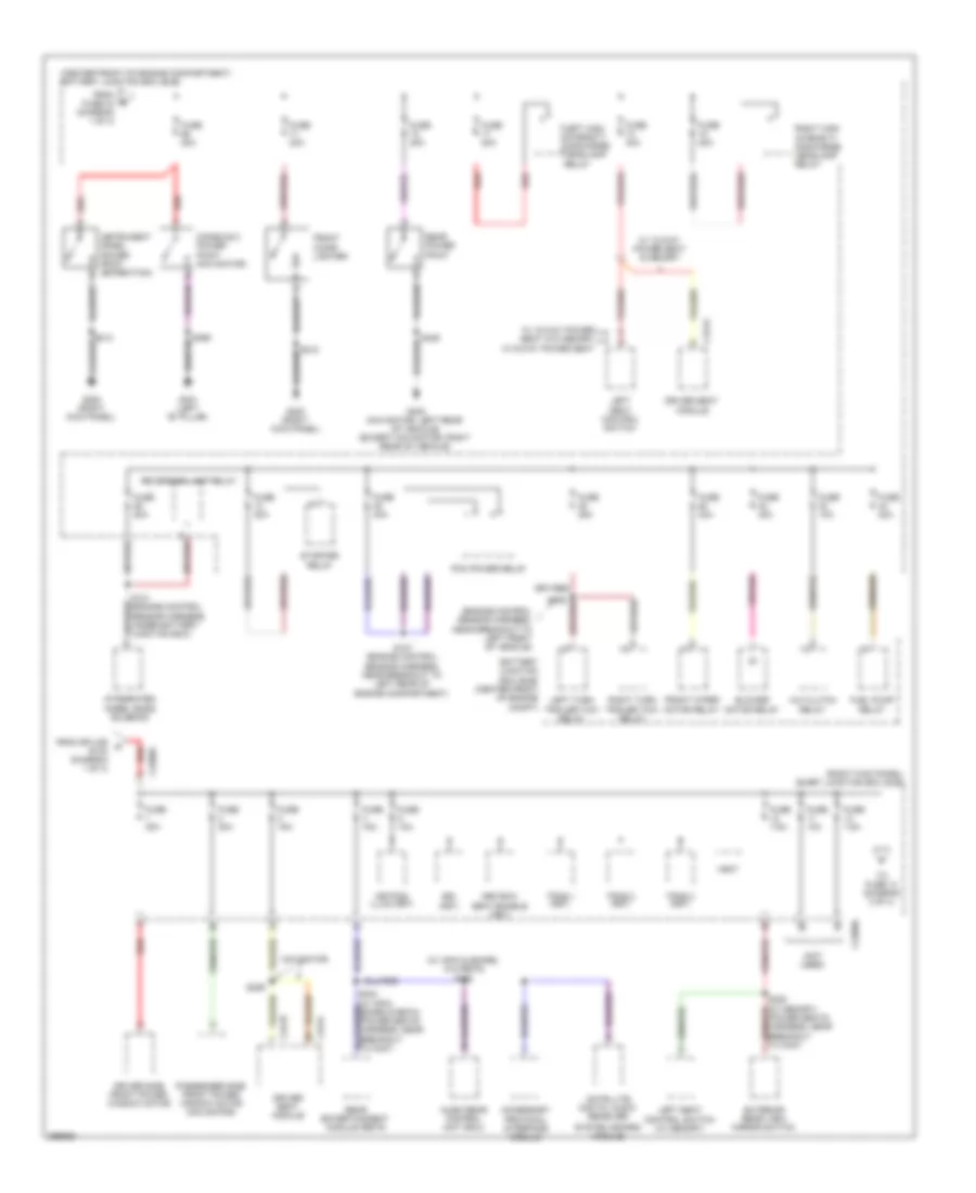
Power Distribution Wiring Diagram (1 of 4) for Lincoln Navigator 2009

List of elements for Power Distribution Wiring Diagram (1 of 4) for Lincoln Navigator 2009:
- (alternator rectifier system harness, near right side of engine compartment) s149
- (center front of engine compartment) battery junction box (bjb)
- (engine control sensor harness, under battery junction box) s114
- 4x4 control module
- Air suspension compressor relay
- Anti-lock brake system (abs) module
- Automatic transmission
- Auxiliary blower motor relay 1
- Auxiliary relay box 2 (right rear corner of vehicle)
- Battery
- Battery charge trailer tow relay
- Brake pedal position switch
- C102a
- C175b
- C2131a
- C281b
- C3265a
- C3313b
- C4174a
- Charge harness, near breakout to top of left cylinder head)
- Console 1 power point
- Dual climate controlled seat module (dcsm)
- Evap canister vent solenoid
- Fuse 10a
- Fuse 15a
- Fuse 20a
- Fuse 20a (expedition)
- Fuse 25a
- Fuse 30a
- Fuse 40a
- Fuse 60a
- Fusible link d (10 ga- red)
- G107 (right rear of engine compartment)
- G301 (left "b" pillar)
- Generator
- Parking lamp trailer tow relay
- Power liftgate module
- Power running board module
- Powertrain control module (pcm)
- Rear window defrost relay
- Red
- Right seat control switch
- Roof opening panel module
- Run/ start relay
- S102
- S104 red (engine control sensor harness, near breakout to c140)
- S105 (engine control sensor harness, near breakout red to c140)
- S148
- S159
- Starter motor
- Third row power fold seat relay
- To fuse 1 smart junction box (sjb) (diagram 2 of 4)
- To fuse 52 (diagram 4 of 4)
- To fuse 55 (diagram 4 of 4)
- To fuse 65 (diagram 2 of 4)
- To splice s212 (diagram 4 of 4)
- Trailer brake control module
- Vehicle dynamics module (vdm)
- W/ 10-way power seat
- W/ 6-way power seat
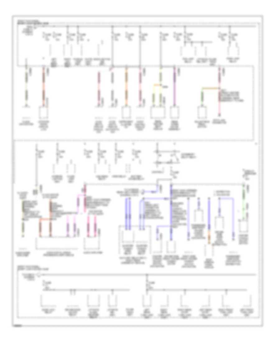
Power Distribution Wiring Diagram (2 of 4) for Lincoln Navigator 2009
List of elements for Power Distribution Wiring Diagram (2 of 4) for Lincoln Navigator 2009:
- (center front of engine compartment) battery junction box (bjb)
- (engine control sensor harness, near breakout to left front of vehicle)
- (not used)
- (right kick panel) smart junction box (sjb)
- (w/ apim & sdars, w/o retm) s382
- 3rd row seat enable (fet)
- A/c clutch relay
- Accessory protocol interface module
- Audio rear control unit (rcu)
- Battery junction box (bjb) (center front of engine compt)
- Blower motor relay
- Bsi (fet)
- C2280d
- C2280g
- C341a
- C341b
- C341c
- Console 2 power point (navigator)
- Driver seat module
- Driver side front power window motor
- Exterior rear view mirror switch
- From fuse 43 (diagram 1 of 4)
- From splice a s104 (diagram 1 of 4)
- Front cigar lighter
- Front wiper motor relay
- Fuel pump relay
- Fuse 10a
- Fuse 15a
- Fuse 20a
- Fuse 25a
- Fuse 30a
- Fuse 40a
- Fuse 7.5a
- G200 (right kick panel)
- G301 (left "b" pillar)
- G402 (navigator: left rear of vehicle) (except navigator: right rear of vehicle)
- Instrument panel power point (expedition)
- Integrated wheel ends solenoid
- Keypad illum (fet)
- Left high intensity discharge headlamp relay
- Left seat control switch
- Left seat control switch (w/ memory)
- Left turn trailer tow relay
- Navigator
- Passenger side front power window motor (navigator)
- Pcm power relay
- Rear entertainment module (retm)
- Rear power point
- Red
- Reversing lamp relay
- Right high intensity discharge headlamp relay
- Right turn trailer tow relay
- S121 (engine control sensor harness, under battery junction box)
- S125
- S127 (engine control sensor harness, near breakout to left rear of engine compartment)
- S359
- S429
- Satellite digital audio receiver
- Starter relay
- System (sdars) module
- To fuse 14 (diagram 3 of 4)
- Tpms 1 (fet)
- Tpms 2 (fet)
- Tpms 3 (fet)
- Vbat
- W/ 10-way power seat & memory
- W/ 10-way power seat w/o memory
- W/ 6-way power seat
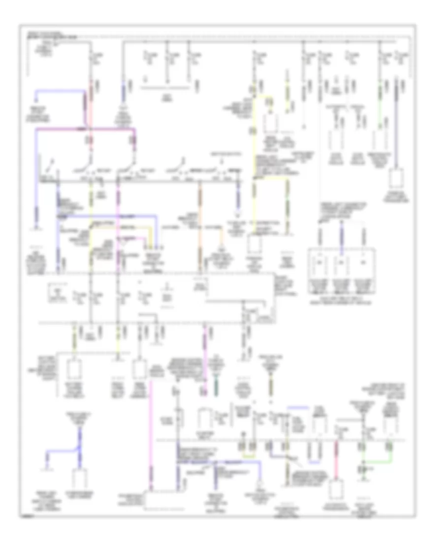
Power Distribution Wiring Diagram (3 of 4) for Lincoln Navigator 2009
List of elements for Power Distribution Wiring Diagram (3 of 4) for Lincoln Navigator 2009:
- (driver's door window regulator harness, in breakout to driver's door) (navigator) s500
- (right kick panel) smart junction box (sjb)
- 25a
- Accessory delay relay
- Adjustable pedal switch
- Audio amplifier
- Audio control module (acm)
- Audio digital signal processing (dsp) module
- Auxiliary relay box 2 (right rear corner of vehicle)
- Backlighting led (fet)
- Battery saver relay
- C2280a
- C2280b
- C2280d
- C228a
- C2357a
- C2364a
- C2385b
- C240a
- C3054b
- C4174a
- C504a
- C535a
- C535b
- Circuit breaker 30a
- Clock (navigator)
- Control
- Data link connector
- Door lock relay
- Driver door unlock relay
- Driver side door lock switch (expedition)
- Driver side front power window motor
- Expedition
- Floor lamp (fet)
- Fog lamp relay
- From f fuse 13 (diagram 2 of 4)
- Fuse
- Fuse 10a
- Fuse 15a
- Fuse 20a
- High beam relay
- Horn relay
- Hvac (datc) module (automatic a/c)
- Hvac (emtc) module (manual a/c)
- Instrument cluster (ic)
- Interior lighting (fet)
- Left front turn lamp (fet)
- Left low beam (fet)
- Left rear stop/ turn lamp (fet)
- Left rear turn lamp (fet)
- Liftgate glass release relay
- Liftgate rel (fet)
- Liftgate/ trunk module (ltm)
- Master window adjust switch
- Master window adjust switch (navigator)
- Navigator
- Navigator w/ thx audio
- Near breakout to passenger's door) s601
- Park lamp relay
- Passenger side door lock switch (expedition)
- Passenger side front power window motor (navigator)
- Puddle lamp (fet)
- Pulse train (fet)
- Quarter window close relay
- Quarter window open relay
- Rear heated seat module
- Rear wiper motor assembly
- Right front turn lamp (fet)
- Right low beam (fet)
- Right rear stop/ turn lamp (fet)
- Right rear turn lamp (fet)
- Right side front power window switch (navigator)
- Roof opening panel module
- S209 (body main harness, near breakout to below right side of dash)
- S217 (front heater blower motor harness, near breakout to c299)
- S366
- Subwoofer amplifier
- To fuse 27 (diagram 4 of 4)
- To interior rear view mirror (diagram 4 of 4)
- W/ audio- phile audio
- W/ navigator & thx audio
- White light (fet)
Power Distribution Wiring Diagram (4 of 4) for Lincoln Navigator 2009
List of elements for Power Distribution Wiring Diagram (4 of 4) for Lincoln Navigator 2009:
- (center front of engine compartment) battery junction box (bjb)
- (engine control sensor harness, near breakout to center front of engine compt) s107
- (engine control sensor harness, under battery junction box) c175b
- (except expedition)
- (expedition)
- (near breakout to g203) s212
- (near breakout to left front wheel speed sensor) s106
- (near breakout to steering column) s257
- (not used)
- (rear light connector harness, in breakout to right side of loading space) s420
- (rear light connector harness, near breakout to left "c" pillar) (w/ rear view camera) s408
- (right kick panel) smart junction box (sjb)
- 4x4 control module
- Acc
- Anti-lock brake system (abs) module
- Audio control module (acm)
- Automatic transmission
- Auxiliary blower motor relay 1
- Auxiliary blower motor relay 2
- Auxiliary blower motor relay 3
- Auxiliary relay box 2 (right rear corner of vehicle)
- Battery charge trailer tow relay
- Battery junction box (bjb) (center front of engine compt)
- Blower motor relay
- C175b
- C2280a
- C2280b
- C2280d
- C2280e
- C228a
- C2357a
- C240a
- C281a
- C310a
- Equipped
- From fuse 41 (diagram 3 of 4)
- From fuse 53 (diagram 1 of 4) c
- From fuse 56 (diagram 4 of 4)
- From h fuse 17 (diagram 3 of 4)
- From ignition switch (diagram 4 of 4)
- From run/ start relay (diagram 1 of 4)
- From splice s117 (diagram 1 of 4)
- Front wiper motor relay
- Fuel pump motor diode
- Fuel pump relay
- Fuse 10a
- Fuse 20a
- Fuse 30a
- Fuse 5a
- Fuse 7.5a
- Hvac (datc) module
- Hvac (eatc) module
- If equipped
- Ignition switch
- Instrument cluster (ic)
- Interior rear view mirror
- Key in ignition
- Key release interlock actuator (w/ floor shifter)
- Lock
- Micro
- Parking aid module (pam)
- Passive anti-theft transceiver
- Powertrain control module (pcm)
- Rain sensor module
- Rear heated seat module
- Rear view camera
- Rear view camera display mirror (w/ rear video camera)
- Rear window defrost relay
- Rear wiper motor assembly
- Remote start connector (if equipped)
- Restraints control module (rcm)
- Run
- Run/ accy
- Run/ start
- S119
- S120
- S229
- S258 (near breakout to center of dash)
- S259 (near breakout to c238)
- S316 (body main harness, near breakout to g301)
- Smart junction box (sjb) (right kick panel)
- Start
- Start diode
- Starter relay
- Tan
- To fuse 30 (diagram 4 of 4)
- To splice s261 (diagram 4 of 4)