POWER DISTRIBUTION
Power Distribution Wiring Diagram (1 of 5) for Mercedes-Benz C300 Luxury 4Matic 2011

List of elements for Power Distribution Wiring Diagram (1 of 5) for Mercedes-Benz C300 Luxury 4Matic 2011:
- (left side of trunk/cargo area) rear sam control unit w/ fuse & relay module
- (not used)
- (right rear of engine compt) front electrical prefuse box
- 30g
- A/c housing (w/ 2-zone thermotronic & 3-zone thermotronic)
- Additional battery relay (w/ start stop function)
- Alternator
- Battery sensor
- C12i
- C30
- C3i
- C7i
- C8d
- C9i
- Combustion engine & air conditioning w/ integrated control fan motor
- Electrohydraulic power steering (glk-class) electronic power steering control module (c-class)
- From fuse 158 a (diagram 1 of 5)
- Front electrical prefuse box (at right rear of engine compt)
- Fuse 100a
- Fuse 150a
- Fuse 200a
- Fuse 25a
- Fuse 400a 200a
- Fuse 40a
- Fuse 50a
- Fuse 50a 100a
- Fuse 60a
- Fuse 7.5a
- Fuse 80a
- Fuse res
- Ig1
- Im1
- Interior protection & tow away protection control unit (if equipped)
- Mg2
- Mr1
- Mr2
- Mr3
- Mr4
- Mr5
- Mr6
- Mr7
- Mr8
- Mr9
- On-board electrical system batetry
- Quiescent current cutout relay
- Rear window antenna fm antenna amplifier (w/ radio), fm, am & cl (zv) antenna amplifier (glk-class)
- Red
- Rss aus
- Rss ein
- Starter
- Stop function
- Tailgate control unit (w/ automatic tailgate)
- Terminal block (circuit 30) (w/ start/stop function)
- To circuit 15 relay (diagram 2 of 5)
- To dc/ac converter control unit (diagram 3 of 5)
- To front sam control unit w/ fuse & relay module (diagram 4 of 5)
- To front sam control unit w/ fuse & relay module (diagram 5 of 5)
- To fuse 150 (diagram 1 of 5)
- To fuse 89 (diagram 2 of 5)
- W/ eco start/ stop function
- W/o eco start/
- W7 (right side of cargo area/ trunk)
- W7 (right side of cargo area/trunk)
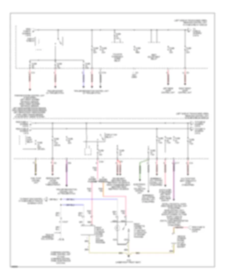
Power Distribution Wiring Diagram (2 of 5) for Mercedes-Benz C300 Luxury 4Matic 2011
List of elements for Power Distribution Wiring Diagram (2 of 5) for Mercedes-Benz C300 Luxury 4Matic 2011:
- (diagram 1 of 5)
- (left side of trunk/cargo area) rear sam control unit w/ fuse & relay module
- (not used)
- C11t
- C12i
- C13a
- C15h
- C3i
- C89
- Circuit 15 relay
- Circuit 15r relay 1
- Driver seat neck-pro head restraint solenoid & front passenger seat neck-pro head restraint solenoid
- Dvd player (if equipped) left rear display & right rear display
- Electronic toll collection control unit
- Emergency call system control unit (if equipped)
- From fuse 41 (diagram g 2 0f 5)
- From fuse 46 c (diagram 1 0f 5)
- From fuse 61 b
- From fuse 76 (diagram 3 0f 5)
- Front cigarette lighter w/ ashtray illumination (w/ smoker package)
- Front vehicle interior power outlet (w/o smoker package)
- Fuel pump control unit
- Fuel pump relay
- Fuse 15a
- Fuse 20a
- Fuse 20a (or 25a)
- Fuse 30a
- Fuse 5a
- Fuse 7.5a
- Fuse 7.5a (or 5a)
- Fuse res
- Left rear door control unit
- Multicontour seat pneumatic pump (if equipped)
- Nca
- Overhead control panel control unit (w/ can) overhead control panel electronics (w/o can)
- Parking system control unit (if equipped), left front bumper distronic sensor, right front bumper distronic sensor, left rear bumper radar sensor, right rear bumper radar sensor, left rear & right rear bumper intelligent radar sensor (w/ blind spot assist system)
- Rear blower motor (w/ 3-zone thermotronic)
- Red
- Right front door control unit
- Seat adjustment relay
- Tailgate windshield wiper relay
- Tele aid emergency call system
- To front sam control w/ fuse & relay module (diagram 4 of 5)
- To fuse 42 (diagram 2 of 5)
- To fuse 74 (diagram 3 0f 5)
- To fuse 85 (diagram 3 0f 5)
- Trailer recognition control unit (w/ trailer hitch)
- Trailer socket (w/ trailer hitch)
- Vehicle interior power outlet (w/ rear socket)
- W/ smoker package
- W/o smoker package
- W19 (under right front seat)
- X18/37
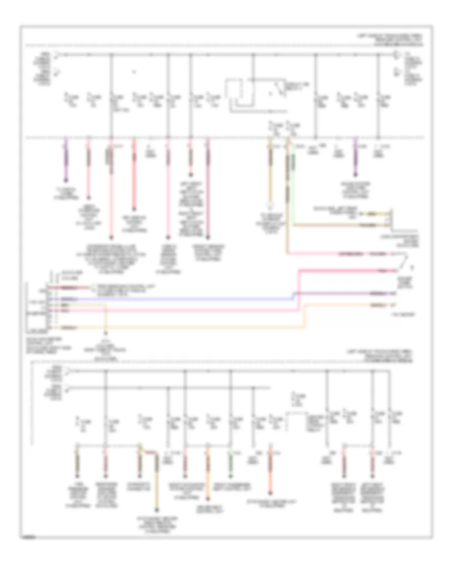
Power Distribution Wiring Diagram (3 of 5) for Mercedes-Benz C300 Luxury 4Matic 2011
List of elements for Power Distribution Wiring Diagram (3 of 5) for Mercedes-Benz C300 Luxury 4Matic 2011:
- (glk-class: left rear cargo panel) w6/1
- (left side of trunk/cargo area) rear sam control unit w/ fuse & relay module
- (not used)
- 115v ac1
- 115v ac2
- 115v socket
- 30g
- Adaptive damping system control unit (if equipped)
- C-class
- C11r
- C11t
- C12i
- C13a
- C14i
- C15h
- C2g
- C66
- C88
- C90
- Circuit 15r relay 2
- Compensator/cellular telephone system umts (w/ mobile phone preinstallation w/ universal interface & w/ stationary heater) tv digital tuner (if equipped)
- Dc/ac converter control unit (glk-class: right side of cargo area)
- Diagnostic connector
- Driver seat control unit
- From fuse 60 (diagram 2 of 5) from fuse 87 (diagram 2 of 5)
- From fuse 67 j (diagram 3 0f 5)
- From fuse 74 (diagram 3 0f 5)
- From rear sam control unit w/ fuse & relay module (diagram 1 of 5)
- Front passenger seat control unit
- Fuse 15a
- Fuse 20a
- Fuse 30a
- Fuse 40a
- Fuse 50a
- Fuse 5a
- Fuse 5a (or 7.5a)
- Fuse 7.5a
- Fuse res
- Glk-class
- Heated rear window relay
- Inverter
- Keyless go control unit (if equipped)
- Left front reversible emergency tensioning retractor (if equipped)
- Left front seat ventilation blower regulator (if equipped) & right front seat ventilation blower regulator (if equipped)
- Load compartment socket (glk-class)
- Media interface control unit (w/ auxiliary jack)
- Pnk
- Rear bass speaker amplifier (w/ sound system) (glk-class)
- Red
- Right front reversible emergency tensioning retractor (if equipped)
- Socket micro- switch
- Sound system amplifier control unit (if equipped)
- Stationary heater radio remote control receiver (if equipped)
- Stationary heater unit (if equipped)
- Tire pressure monitor control unit (if equipped)
- To fuse 70 (diagram 3 of 5) to fuse 73 (diagram 3 of 5)
- To vehicle interior power outlet (daigram 2 of 5)
- Tv digital tuner (if equipped)
- Video & radar sensor system control unit (if equipped)
- W7/1 (c-class) (right side of trunk) w7/2 (glk-class)
- Weight sensing system (wss) control unit (if equipped)
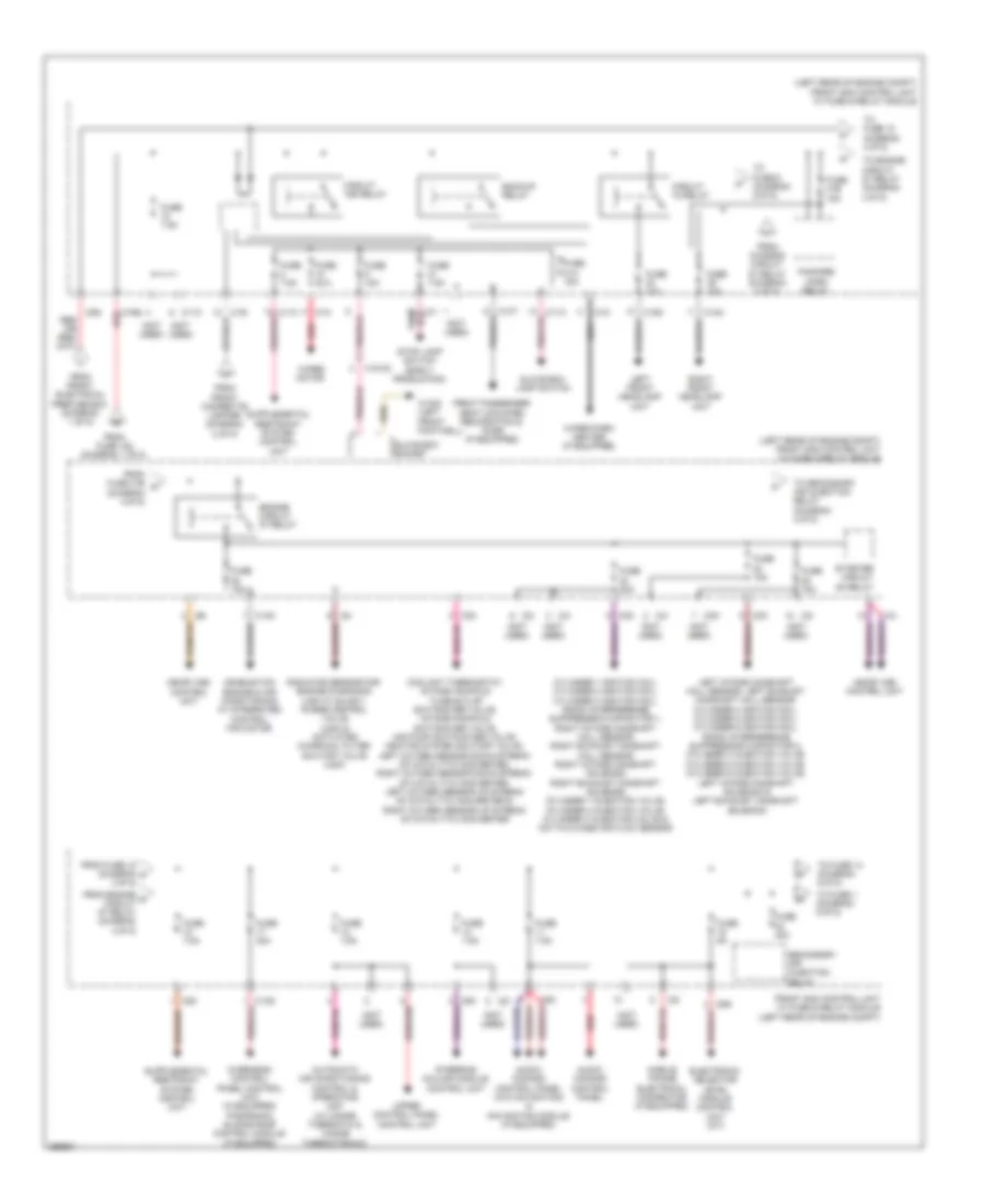
Power Distribution Wiring Diagram (4 of 5) for Mercedes-Benz C300 Luxury 4Matic 2011
List of elements for Power Distribution Wiring Diagram (4 of 5) for Mercedes-Benz C300 Luxury 4Matic 2011:
- (diagram 4 0f 5)
- (left rear of engine compt) front sam control unit w/ fuse & relay module
- (not used)
- Audio/ comand control panel
- Audio/ comand control panel (w/o navigation) & navigation module (if equipped)
- Automatic air conditioning control & operating unit (w/ 2-zone thermatic & 3-zone thermotronic)
- Backup relay
- C10t
- C11c
- C13d
- C14m
- C15m
- C16s
- C19i
- C1m
- C2i
- C3m
- C4i
- C5c
- C6i
- C7i
- C8s
- C9g
- Circuit 15 relay
- Circuit 15r relay
- Combustion engine & air conditioning w/ integrated control fan motor
- Coolant thermostat, intake manifold tumble flap switchover valve, intake manifold switchover valve, air pump switchover valve, heating system shutoff valve, left oxygen sensor down stream of catalytic converter, right oxygen sensor down stream of catalytic converter, left oxygen sensor up stream of catalytic converter & right oxygen sensor up stream of catalytic converter
- Cylinder 1 ignition coil, cylinder 2 ignition coil, cylinder 3 ignition coil, radio interference suppression capacitor 1, right intake camshaft hall sensor, right exhaust camshaft hall sensor, right intake camshaft solenoid, right exhaust camshaft solenoid, cylinder 1 injection valve, cylinder 2 injection valve, cylinder 3 injection valve & hot film mass air flow sensor
- Electronic selector level module control unit (a/t)
- Engine circuit 87 relay
- Fanfare horn relay
- From chassis circuit 87 relay (diagram 5 0f 5)
- From engine o circuit 87 relay (diagram 4 0f 5)
- From front cigarette lighter (diagram 2 of 5)
- From front electrical prefuse box (diagram 1 of 5)
- From fuse 152 (diagram 1 of 5)
- From fuse 18 (diagram m 4 0f 5)
- From fuse 31b n
- Front passenger seat occupied recognition & acsr (if equipped)
- Front sam control unit w/ fuse & relay module (left rear of engine compt)
- Fuse 10a
- Fuse 15a
- Fuse 20a
- Fuse 30a
- Fuse 31a 15a
- Fuse 31b 15a
- Fuse 40a
- Fuse 5a
- Fuse 7.5a
- Glove box lamp switch
- Glove box socket
- Left front headlamp unit
- Left intake camshaft hall sensor, left exhaust camshaft hall sensor, cylinder 4 ignition coil, cylinder 5 ignition coil, cylinder 6 ignition coil, radio interference suppression capacitor 2, cylinder 4 injection valve, cylinder 5 injection valve, cylinder 6 injection valve, left intake camshaft solenoid & left exhaust camshaft solenoid
- Me-sfi (me) control unit
- Mobile phone electrical connector (if equipped)
- Nca
- Overhead control panel control unit (if equipped) panoramic sliding roof control module (if equipped)
- Radiator sensor for engine diagnosis (usa w/ sulev), purge control valve (usa) & activated charcoal filter shutoff valve (usa)
- Red
- Right front headlamp unit
- Secondary air injection relay
- Starter circuit 50 relay
- Steering column module control unit
- Stop lamp switch (early production)
- To engine circuit 87 relay (diagram 4 0f 5)
- To fuse 1 (diagram 5 0f 5)
- To fuse 14 (diagram 5 0f 5)
- To fuse 15 (diagram 4 0f 5)
- To fuse 6 (diagram 5 0f 5)
- To secondary air injection relay (diagram 4 0f 5)
- Upper control panel control unit
- W15/5 (left front footwell)
- Wiper motor
- Wiper park heater (if equipped)
- X18-c2
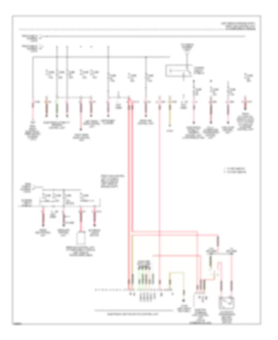
Power Distribution Wiring Diagram (5 of 5) for Mercedes-Benz C300 Luxury 4Matic 2011
List of elements for Power Distribution Wiring Diagram (5 of 5) for Mercedes-Benz C300 Luxury 4Matic 2011:
- (left rear of engine compt) front sam control unit w/ fuse & relay module
- (not used)
- 30z
- Automatic transmission neutral position switch
- C-class
- C10t
- C11c
- C12s
- C15m
- C2i
- C4i
- C5c
- C6i
- C7i
- C9g
- C9i
- Can-b h
- Can-b l
- Can-e h
- Can-e l
- Chassis circuit 87 relay
- Computer data lines system
- Data
- Electric steering lock control unit (top of steering column)
- Electronic ignition switch control unit
- Electronic stability program control unit
- Electronic stability program control unit (late production)
- Exterior lights switch
- From front electrical prefuse box (diagram 1 of 5)
- From fuse 16 (diagram 4 of 5)
- From fuse 29 (diagram 4 of 5)
- From fuse 32 (diagram 4 of 5)
- Front sam control unit w/ fuse & relay module (left rear of engine compt)
- Fuel pump control unit
- Fully integrated transmission control unit
- Fuse 10a
- Fuse 20a
- Fuse 25a
- Fuse 30a
- Fuse 40a
- Fuse 5a
- Fuse 7.5a
- Fuse 7.5a (or 20a)
- Headlamp control unit
- Instrument cluster
- Left front door control unit
- Me-sfi (me) control unit
- Pnk
- Pnk/red
- Radio (w/ audio 20), radio w/ auto pilot system (w/ audio 50) & comand control unit
- Rear sam control unit w/ fuse & relay module (left side of trunk/cargo area)
- Red
- Right rear door control unit
- Starter circuit 50 relay
- To fuse 29 (diagram 4 of 5)
- W/ keyless go
- W/o keyless go
- W15/5 (left front footwell)
- W16/3