POWER DISTRIBUTION
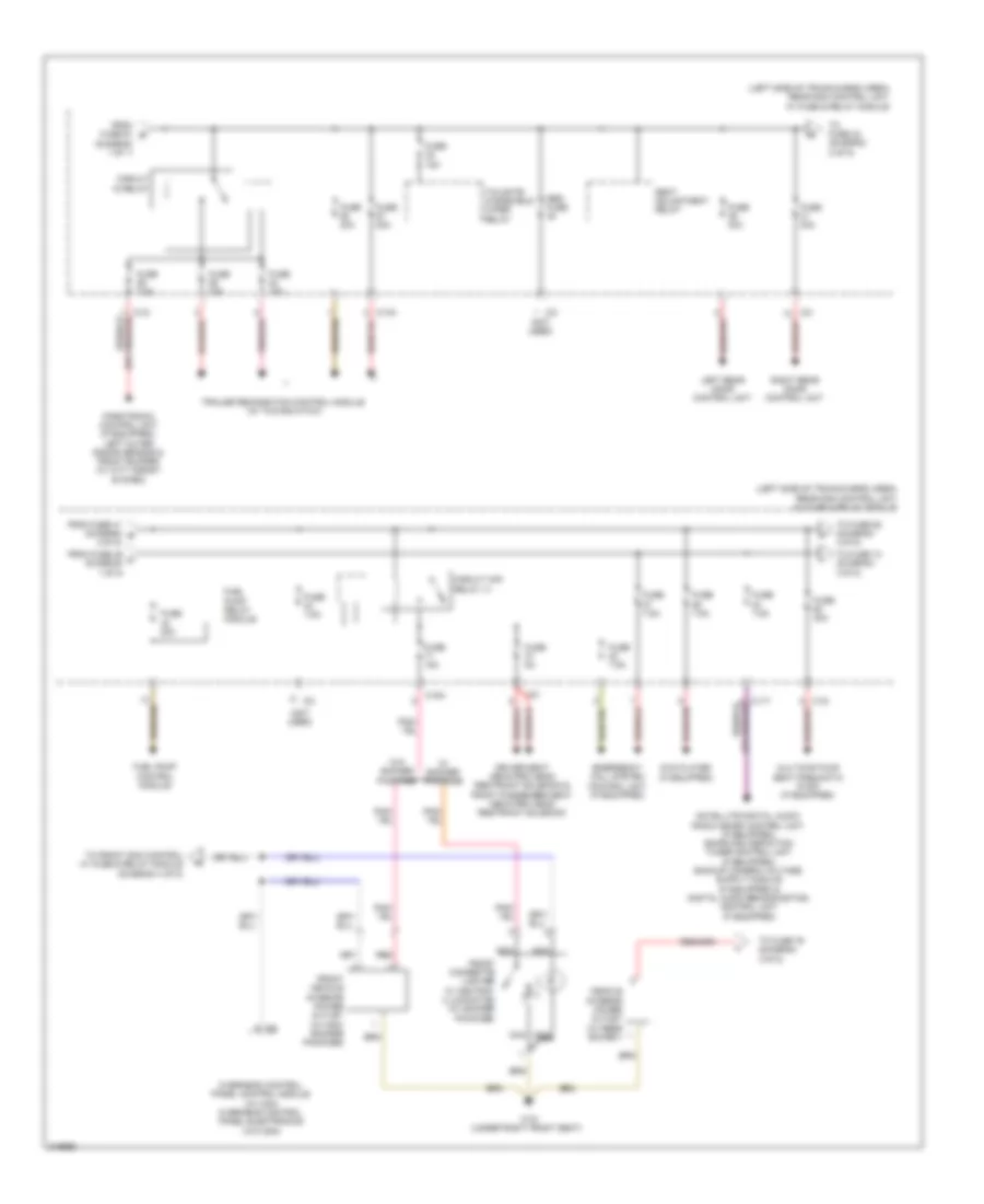
Power Distribution Wiring Diagram (1 of 5) for Mercedes-Benz C350 Sport 2009

List of elements for Power Distribution Wiring Diagram (1 of 5) for Mercedes-Benz C350 Sport 2009:
- (behind left end of dash) interior fuse box
- (not used)
- (right side of luggage compt) rear prefuse box
- A c112
- A c115
- A/c housing
- Adaptive damping system control unit (if equipped)
- Alarm siren (if equipped)
- Battery
- Battery sensor
- C111 e
- C112
- C113 a
- C114 a
- C115
- C116
- C117
- C126
- C128
- C12i
- C1v
- C2v
- C3i
- C7l
- C8d
- C9i
- Combustion engine & air conditioning w/ integrated control fan motor
- Cp1
- Cp2
- Cp3
- Driver seat control unit
- From fuse 103 a (diagram 1 of 1)
- Front electrical prefuse box (at right rear of engine compt)
- Front passenger seat control unit
- Fuse 100a
- Fuse 125a
- Fuse 150a
- Fuse 15a
- Fuse 200a
- Fuse 20a
- Fuse 25a
- Fuse 30a
- Fuse 400a
- Fuse 40a
- Fuse 60a
- Fuse 7.5a
- Fuse 70a
- Fuse 80a
- Fuse res
- Generator
- Interior protection & tow away protection control unit (if equipped)
- Quiescent current cutout relay
- Rear blower motor (w/ thermotronic)
- Rear sam control unit w/ fuse & relay module (left side of trunk/cargo area)
- Rear window antenna fm antenna amplifier (w/ radio), rear window antenna amplifier 1, dab band iii antenna & tv1 & dab band iii antenna (w/ digital audio broad casting), tv2 & keyless go antenna amplifier (if equipped)
- Red
- Res fuse
- Rss aus
- Rss ein
- Special purpose vehicle multi-function control unit (w/ taxi)
- Starter
- Tailgate control unit (w/ automatic tailgate)
- To circuit 15 relay (diagram 2 of 5)
- To fuse (diagram 4 of 5)
- To fuse (diagram 5 of 5)
- To fuse 108 (diagram 1 of 5)
- To fuse 87 (diagram 2 of 5)
- W7 (right side of trunk)
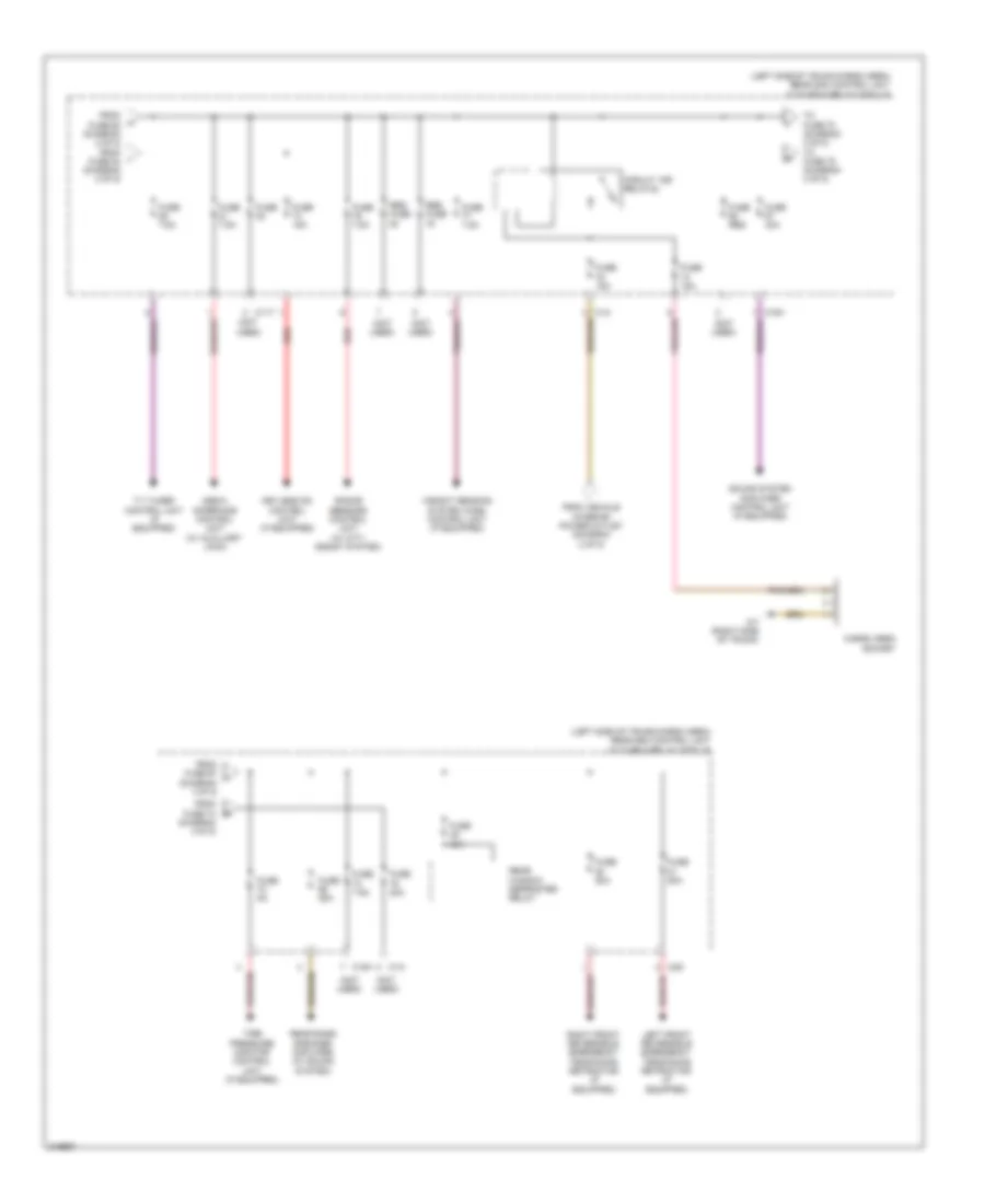
Power Distribution Wiring Diagram (2 of 5) for Mercedes-Benz C350 Sport 2009
List of elements for Power Distribution Wiring Diagram (2 of 5) for Mercedes-Benz C350 Sport 2009:
- (diagram 1 of 1)
- (left side of trunk/cargo area) rear sam control unit w/ fuse & relay module
- (not used)
- (or pnk/red)
- C11t
- C12i
- C13a
- C15h
- C3i
- Circuit 15 relay
- Circuit 15r relay (1)
- Driver seat neck-pro head restraint solenoid & front passenger seat neck-pro head restraint solenoid
- Dvd player (if equipped)
- Emergency call system control unit (if equipped)
- From fuse 41 (diagram g 2 0f 5)
- From fuse 46 c (diagram 1 0f 5)
- From fuse 61 b
- Front cigarette lighter w/ ashtray illumination (w/ smoker package)
- Front vehicle interior power outlet (w/ non- smoker package)
- Fuel pump control module
- Fuel pump relay module
- Fuse 15a
- Fuse 20a
- Fuse 30a
- Fuse 5a
- Fuse 7.5a
- Left rear door control unit
- Multicontour seat pneumatic pump (if equipped)
- Nca
- Overhead control panel control module (w/ can) overhead control panel electronics (w/o can)
- Parktronic control unit (if equipped), left outer radar sensor & front bumper (w/ city assist system)
- Pnk/red
- Red
- Res fuse
- Right rear door control unit
- Seat adjustment relay
- Tailgate windshield wiper relay
- To front sam control w/ fuse & relay module (diagram 4 of 5)
- To fuse 42 (diagram 2 of 5)
- To fuse 74 (diagram 3 0f 5)
- To fuse 76 (diagram 3 0f 5)
- To fuse 85 (diagram 3 0f 5)
- Trailer recognition control module (w/ towing hitch)
- Vehicle interior power outlet (w/ rear socket)
- W/ smoker package
- W/o smoker package
- W19 (under right front seat)
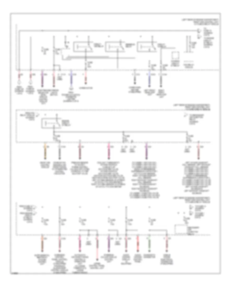
Power Distribution Wiring Diagram (3 of 5) for Mercedes-Benz C350 Sport 2009
List of elements for Power Distribution Wiring Diagram (3 of 5) for Mercedes-Benz C350 Sport 2009:
- (left side of trunk/cargo area) rear sam control unit w/ fuse & relay module
- (not used)
- C11t
- C14i
- C15h
- C2g
- Cargo area socket
- Circuit 15r relay(2)
- From fuse 60 (diagram 2 of 5) from fuse 84 (diagram 2 of 5)
- From fuse 67 j (diagram 3 0f 5)
- From fuse 74 (diagram 3 0f 5)
- From vehicle interior power outlet (daigram 2 of 5)
- Fuse
- Fuse 15a
- Fuse 20a
- Fuse 25a
- Fuse 40a
- Fuse 50a
- Fuse 5a
- Fuse 7.5a
- Fuse res
- Keyless go control unit (if equipped)
- Left front reversible emergency tensioning retractor (if equipped)
- Media interface control unit (w/ auxiliary jack)
- Radar sensors control unit (w/ city assist system)
- Rear bass speaker amplifier (w/ sound system)
- Rear window defroster relay
- Red
- Res fuse
- Right front reversible emergency tensioning retractor (if equipped)
- Sound system amplifier control unit (if equipped)
- Tire pressure monitor control unit (if equipped)
- To fuse 70 (diagram 3 of 5) to fuse 75 (diagram 3 of 5)
- Tv tuner control unit (if equipped)
- W7 (right side of trunk)
- Weight sensing system (wss) control unit (if equipped)
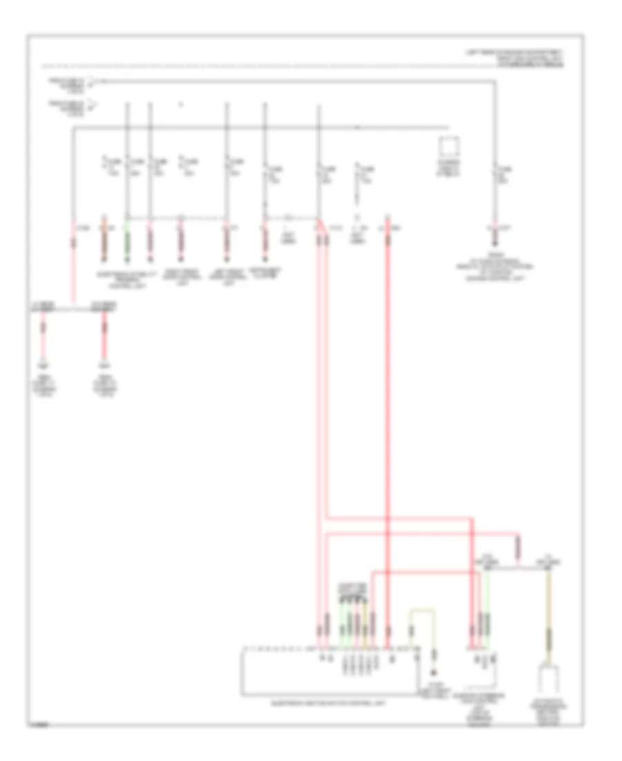
Power Distribution Wiring Diagram (4 of 5) for Mercedes-Benz C350 Sport 2009
List of elements for Power Distribution Wiring Diagram (4 of 5) for Mercedes-Benz C350 Sport 2009:
- (diagram 4 0f 5)
- (left rear of engine compartment) front sam control unit w/ fuse & relay module
- (not used)
- 16s
- Audio/ comand control panel
- Audio/ comand display (if equipped)
- Automatic air conditioning control & operating unit (w/ 2-zone thermatic & 3-zone thermotronic)
- C11c
- C13d
- C14m
- C15m
- C19i
- C1m
- C2i
- C3m
- C4i
- C5c
- C6i
- C9g
- Chassis circuit 87 relay
- Circuit 15 relay
- Circuit 15r relay
- Combustion engine & air conditioning w/ integrated control fan motor
- Coolant thermostat, intake manifold tumble flap switchover valve, intake manifold switchover valve, air pump switchover valve, heating system shutoff valve, left oxygen sensor up stream of catalytic converter & right oxygen sensor up stream of catalytic converter
- Cylinder 1 ignition coil, cylinder 2 ignition coil, cylinder 3 ignition coil, radio interference suppression capacitor 1 hot film maf sensor, right intake camshaft hall sensor, right exhaust camshaft hall sensor, right intake camshaft solenoid, right exhaust camshaft solenoid, cylinder 1 injection valve, cylinder 2 injection valve & cylinder 3 injection valve
- Diagnostic connector
- Electronic selector level module control module (a/t)
- Engine circuit 87 relay
- Exterior lights switch
- Fan relay module
- From engine o circuit 87 relay (diagram 4 0f 5)
- From fan relay module n
- From fuse 105 (diagram 1 of 5)
- From fuse 16 (diagram m 4 0f 5)
- From fuse 89 (diagram 1 of 5)
- From power outlets & cigarette lighter (diagram 2 of 5)
- Fuse 10a
- Fuse 15a
- Fuse 20a
- Fuse 30a
- Fuse 31b 15a
- Fuse 40a
- Fuse 5a
- Fuse 7.5a
- Left front headlamp unit
- Left intake camshaft hall sensor, left exhaust camshaft hall sensor, cylinder 4 ignition coil, cylinder 5 ignition coil, cylinder 6 ignition coil, radio interference suppression capacitor 2, cylinder 4 injection valve, cylinder 5 injection valve, cylinder 6 injection valve, left intake camshaft solenoid & left exhaust camshaft solenoid
- Me-sfi (me) control module
- Mobile phone electrical connector (if equipped)
- Nca
- Overhead control panel control module (if equipped) panoramic sliding roof control module (if equipped)
- Premair sensor (w/ sulev), purge control valve & activated charcoal filter shutoff valve
- Red
- Reserve relay
- Right front headlamp unit
- Secondary air injection relay
- Steering column module control unit
- To engine circuit 87 relay (diagram 4 0f 5)
- To fuse 1 (diagram 5 0f 5)
- To fuse 14 (diagram 5 0f 5)
- To fuse 15 (diagram 4 0f 5)
- To secondary air injection relay (diagram 4 0f 5)
- Upper control panel control unit
- Wiper motor
- Wiper park heater (if equipped)
Power Distribution Wiring Diagram (5 of 5) for Mercedes-Benz C350 Sport 2009
List of elements for Power Distribution Wiring Diagram (5 of 5) for Mercedes-Benz C350 Sport 2009:
- (left rear of engine compartment) front sam control unit w/ fuse & relay module
- (not used)
- 30z
- Automatic transmission neutral position switch
- C10t
- C11c
- C12s
- C2i
- C4i
- C5c
- C7i
- Can-b h
- Can-b l
- Can-e h
- Can-e l
- Chassis circuit 87 relay
- Computer data lines system
- Data
- Electric steering lock control unit (top of steering column)
- Electronic ignition switch control unit
- Electronic stability program control unit
- From fuse 101 (diagram 1 of 5)
- From fuse 111 (diagram 1 of 5)
- From fuse 16 (diagram 4 of 5)
- From fuse 32 (diagram 4 of 5)
- Fuse 20a
- Fuse 25a
- Fuse 30a
- Fuse 40a
- Fuse 7.5a
- Instrument cluster
- Left front door control unit
- Radio (w/ audio 20 radio), radio w/ auto pilot system (w/ audio 50) comand control unit
- Red
- Right front door control unit
- W/ keyless go
- W/ rear battery
- W/o keyless go
- W/o rear battery
- W15/5 (left front footwell)