POWER DISTRIBUTION
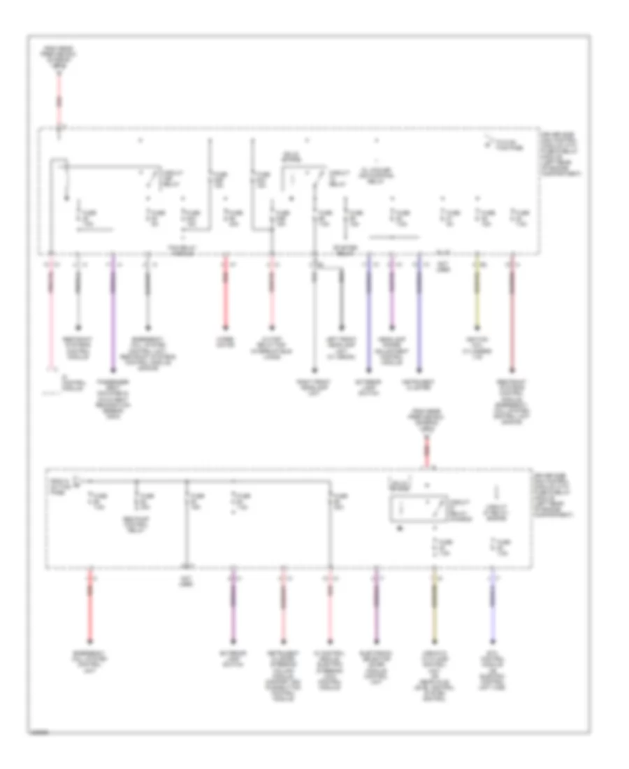
Power Distribution Wiring Diagram (1 of 3) for Mercedes-Benz E320 2005

List of elements for Power Distribution Wiring Diagram (1 of 3) for Mercedes-Benz E320 2005:
- 2003 & 2004 early prod.
- 2003-04
- 2004 late prod., 2005 & 2006
- 2005-06
- Airmatic relay
- Airmatic with ads control module
- Auxiliary battery relay
- Auxiliary battery relay (charging circuit)
- Battery
- Battery control module
- Cd changer
- Central gateway control module
- Cigarette lighter
- Circuit 58d potential splitter
- Comand operating display and control module
- Cutoff relay for inter- ruptible loads
- Data link connector
- Dc/dc converter control module
- Driver front seat adjustment control module with memory
- Driver side sam control module
- Driver side sam control module with fuse/relay module (left rear of engine compartment)
- Driver side sam control panel
- Electric suction fan engine & ac with integrated control
- From d on this page
- From e on this page
- From f on this page
- Front passenger front seat adjustable control module with memory
- Front prefuse box (right front footwell)
- Fuse 100a
- Fuse 150a
- Fuse 15a
- Fuse 15a 5a
- Fuse 200a
- Fuse 25a
- Fuse 30a
- Fuse 40a
- Fuse 50a
- Fuse 5a
- Fuse 7,5a
- Fuse 7.5a
- Heat systems recirculation unit or solar generator control module
- Hs & seat ventilation control module
- Interior fuse box (left end of dash)
- Interior socket
- Left front door control module
- Left front reversible emergency tensioning retractor
- Left rear door control module
- Loading floor control module (wagon)
- Lower control field control module
- Me-sfi control module
- Nca
- Neck-pro head restraint relay
- Passenger side sam control module
- Pneumatic pump for dynamic seat control
- Radio
- Radio control panel & navigation unit
- Rear module keyless go control module, left rear door keyless go control module
- Rear prefuse box (lower right front of trunk)
- Red
- Right front door control module
- Right front reversible emergency tensioning retractor
- Right rear door control module
- Sbc hydraulic unit
- Sdar control
- Starter, generator
- Steering column module
- Telecommunication control module or universal portable ctel interface control module
- Tlc control module
- To d on this page
- To driver side sam control module with fuse & relay module (diagram 2 of 3)
- To e on this page
- To f on this page
- To rear sam control module with fuse & relay module (diagram 3 of 3)
- Upper control panel control module
- Voice control system control module
- W/ comand system
- W/ radio control module
- W/ radio control panel
- W/ radio with aps
- W/o radio control panel
- W15/2 (left front footwell)
- W6 (left rear wheelhousing)
- Weight sensing system control module
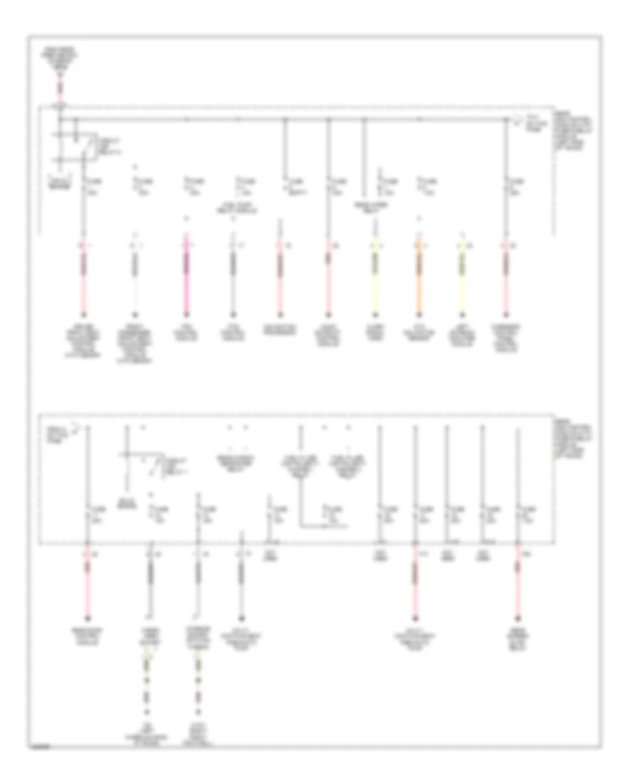
Power Distribution Wiring Diagram (2 of 3) for Mercedes-Benz E320 2005
List of elements for Power Distribution Wiring Diagram (2 of 3) for Mercedes-Benz E320 2005:
- Airmatic with aids control unit or rear axle level control system control
- Circuit 15r relay
- Circuit 87 relay- engine
- Circuit relay
- Circuit relay- chassis
- Cutoff relay for interruptible loads
- Di control module
- Di control module, electric steering lock control module
- Driver side sam control module with fuse & relay module (left rear of engine compartment)
- Electronic selector lever module control unit
- Emergency call system control unit
- Emergency call system control unit, restraint systems control module (2005-06)
- Etc control module or electric control unit (vgs)
- Exterior lamp switch
- Fan relay module
- From g on this page
- From rear prefuse box (diagram 1 of 3)
- Fuse 15a
- Fuse 20a
- Fuse 30a
- Fuse 40a
- Fuse 53a 15a
- Fuse 53b 15a
- Fuse 54a 15a
- Fuse 54b 15a
- Fuse 5a
- Fuse 7.5a
- Headlamp range adjustment control module
- I10
- Ignition coil cylinders (1-6)
- Instrument cluster
- Instrument cluster, steering column module, comfort aac pushbutton control module
- Left front headlamp unit (w/ xenon)
- Not used
- Oil cooler air pump/fan relay
- Passenger seat occupied & child seat recognition sensor (2003)
- Red
- Restraint systems control module
- Restraint systems control module, emergency call system control unit (2005-06)
- Right front headlamp unit
- Seq pump control relay
- Solid state
- Starter relay
- To g on this page
- Wiper motor
Power Distribution Wiring Diagram (3 of 3) for Mercedes-Benz E320 2005
List of elements for Power Distribution Wiring Diagram (3 of 3) for Mercedes-Benz E320 2005:
- Alarm signal horn
- Ata inclination sensor
- Audio gateway control module
- Cargo area socket
- Circuit 15r relay 1
- Circuit 15r relay 2
- Driver front seat adjustment control module with memory
- F17
- F18
- F19
- F20
- From h on this page
- From rear prefuse box (diagram 1 of 3)
- Front passenger front seat adjustment control module with memory
- Fuel filler cap polarity change 1 relay
- Fuel filler cap polarity change 2 relay
- Fuel pump relay module
- Fuse 10a
- Fuse 15a
- Fuse 20a
- Fuse 25a
- Fuse 30a
- Fuse 40a
- Fuse 7.5a
- Fuse empty
- Interior socket (station wagon)
- Left antenna amplifier module
- Multi- contour seat pneumatic pump
- Multi- contour seat pneumatic pump
- Navigation processor
- Not used
- Overhead control panel control module
- Pts control module
- Rear door control module
- Rear sam control module with fuse & relay module (left side of trunk)
- Rear screen blind relay
- Rear window defroster relay
- Rear wiper relay
- Red
- Solid state
- To h on this page
- Tpm control module
- W15/1 (right front footwell)
- W6 (left wheelhousing, in trunk)