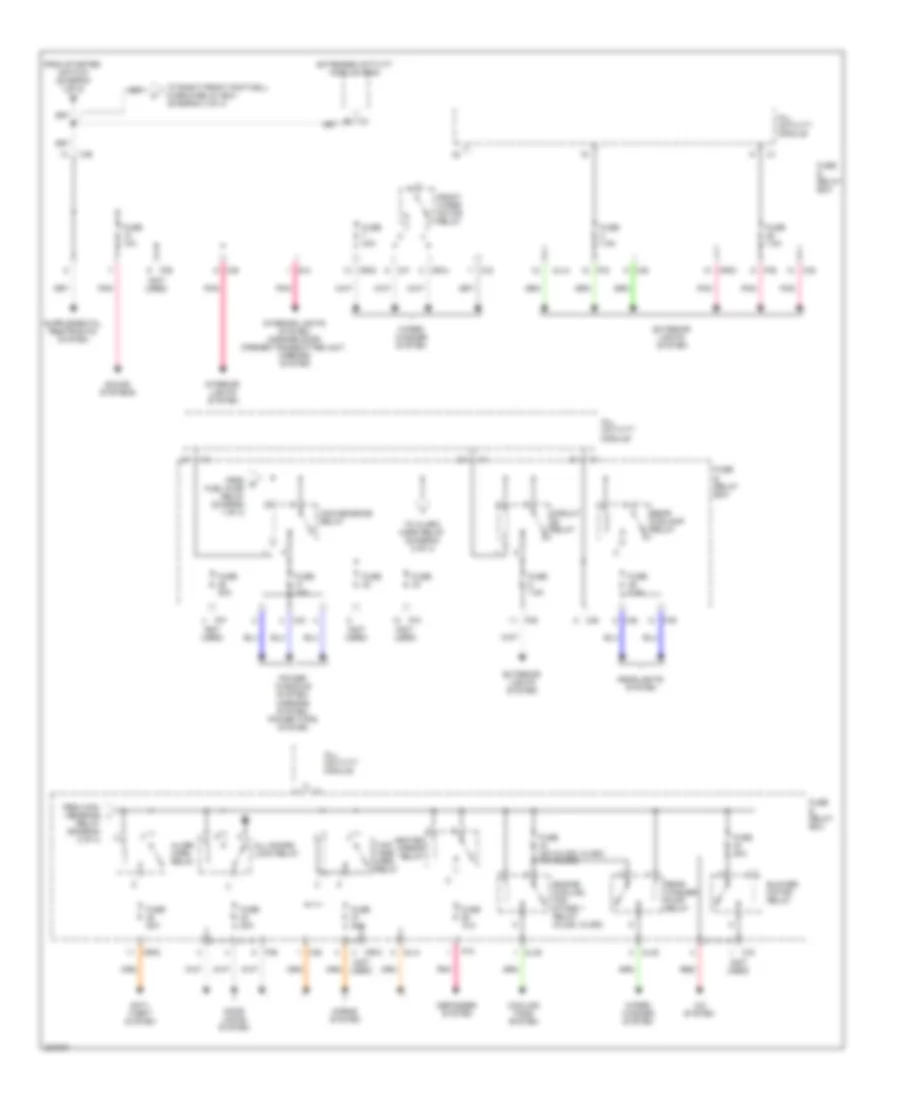
POWER DISTRIBUTION
Power Distribution Wiring Diagram (1 of 4) for Mercedes-Benz ML500 2005

List of elements for Power Distribution Wiring Diagram (1 of 4) for Mercedes-Benz ML500 2005:
- (ml500)
- (not used)
- 15c
- 15r
- A/c system
- A10
- Abs system
- Accy
- All activity module
- Anti- lock brakes system
- Anti-lock brakes system
- Anti-lock brakes system, cooling fans system
- Battery
- C/a
- C/c
- C/d
- C/e
- C/f
- C4 a8
- Circuit relay
- Combination switch
- Cooling fans system
- D/a
- Data link connector (dlc)
- Engine control module (me-sfi)
- Engine controls system
- Engine controls system, power windows system, transmissions system, instrument cluster system, wiper/washer system, mirrors system
- Engine controls systems
- Extended activity module (eam)
- Exterior lights system
- F23
- From battery (diagram 1 of 4)
- From e fuse 18 (diagram 1 of 4)
- From f fuse 19 (diagram 1 of 4)
- From fuse 13 (diagram 1 of 4)
- Fuse
- Fuse & relay box
- Fuse & relay box (in left side of engine compt, in "e" box)
- Fuse 10a
- Fuse 15a
- Fuse 20a
- Fuse 25a
- Fuse 40a
- Generator
- Headlights system
- Instrument cluster
- Instrument cluster system
- Interior lights system
- Interior lights system, instrument cluster system
- M/a
- M/c
- Ml/a
- Mr/a
- Mr/b
- Mr/d
- Mr/e
- Navigation system
- Off
- P/a
- P/b
- P/c
- P/d
- P/e
- P30
- Pnk
- Power tops system
- Red
- Run
- Seats system, memory system
- Secondary air injection pump relay
- Sound systems
- Start
- Starter
- Starter key switch (closed with key in starter switch)
- Starter relay
- Starter switch
- To all activity module (diagram 1 of 4)
- To convenience relay (diagram 2 of 4)
- To extended activity module (diagram 1 of 4)
- To fuse 10 (diagram 2 of 4)
- To fuse 20 (diagram 1 of 4)
- To fuse 21 (diagram 1 of 4)
- To rear foglamp relay (diagram 3 of 4)
- To right front footwell fuse & relay box (diagram 4 of 4)
- Transmission system
- Transmissions system
- W16/4 (right side of firewall)
- X12/12
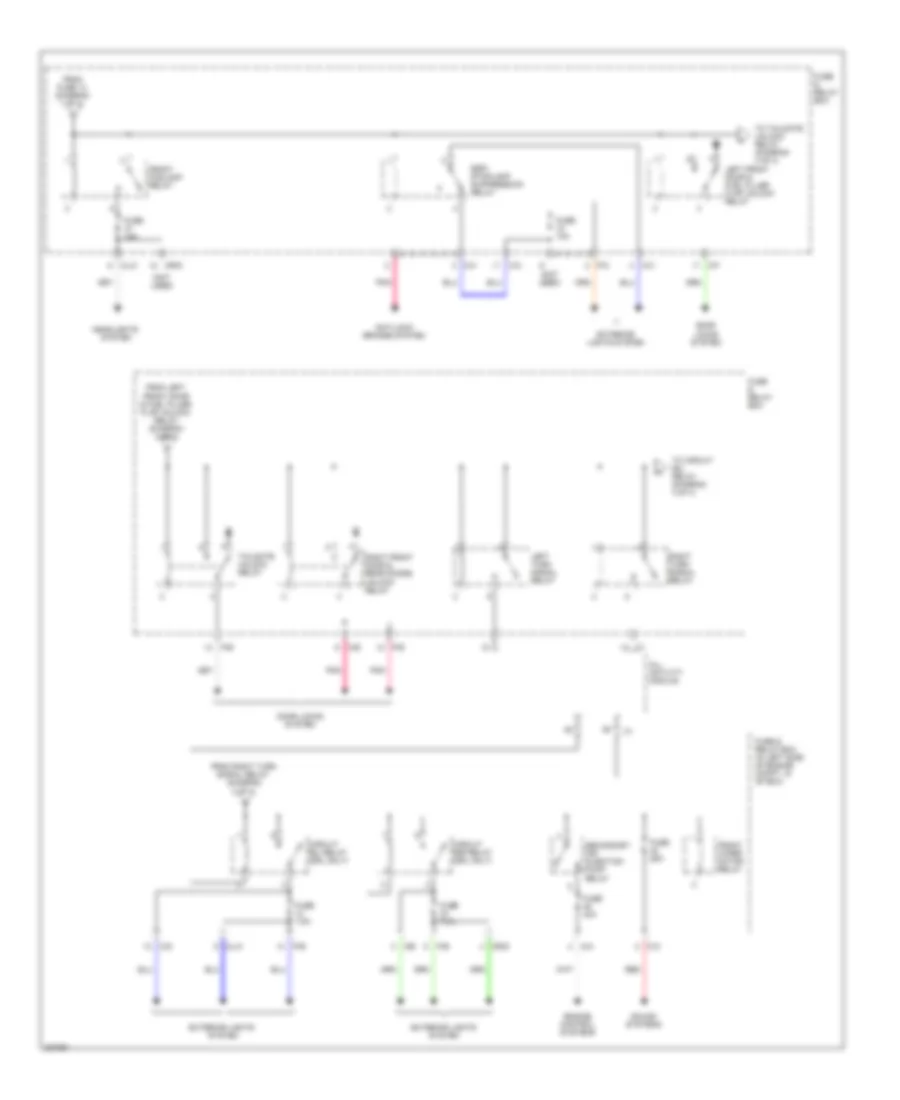
Power Distribution Wiring Diagram (2 of 4) for Mercedes-Benz ML500 2005
List of elements for Power Distribution Wiring Diagram (2 of 4) for Mercedes-Benz ML500 2005:
- (not used)
- A/c system
- Alarm horn relay
- All activity module
- All doors lock relay
- Anti- theft system
- B5 c3
- Blower motor relay
- C/b
- C/d
- C/e
- C/f
- C/g
- Circuit relay
- Convenience relay
- Cooling fans system
- D/a
- Defogger system
- Door locks system
- Engine cooling fan stage 1 relay (ml320, ml350)
- Extended activity module (eam)
- Exterior lights system
- From con- venience i
- From g fuel pump relay (diagram 1 of 4)
- From starter switch (diagram 1 of 4)
- Front wiper motor relay
- Fuse
- Fuse & relay box
- Fuse 10a
- Fuse 15a
- Fuse 20a
- Fuse 30a
- Fuse 40a (ml320, ml350) 15a (ml500)
- Fuse 7.5a
- Headlights system
- Heated mirror relay
- Horns system
- Interior lights system
- Interior lights system, garage door opener transmitter unit, mirrors system
- Ml/a
- Ml/b
- Mr/a
- Mr/c
- Mr/d
- P/a
- P/b
- P/c
- P/d
- P/e
- P/f
- Pnk
- Power windows system, mirrors system, power tops system
- Rear foglamp relay
- Rear washer pump relay
- Red
- Relay (diagram 2 of 4)
- Sound systems
- To alarm horn relay (diagram 2 of 4)
- To right front footwell fuse & relay box (diagram 4 of 4)
- Two- tone horn relay
- Wiper/ washer system
Power Distribution Wiring Diagram (3 of 4) for Mercedes-Benz ML500 2005
List of elements for Power Distribution Wiring Diagram (3 of 4) for Mercedes-Benz ML500 2005:
- (not used)
- All activity module
- Anti-lock brakes system
- C/c
- C/d
- C/e
- C/f
- C/h
- Circuit 58l relay (drl only)
- Circuit 58r relay (drl only)
- Door locks system
- Engine control systems
- Esp/ stoplamp suppression relay
- Exterior lights system
- From fuse 13 (diagram 1 of 4)
- From left front door & fuel filler flap unlock relay (diagram 3 of 4)
- From right turn signal relay (diagram 3 of 4)
- Front foglamp relay
- Front wiper motor relay
- Fuse & relay box
- Fuse & relay box (in left side of engine compt, in "e" box)
- Fuse 10a
- Fuse 15a
- Fuse 25a
- Fuse 40a
- Fuse 7.5a
- Headlights system
- K10
- Left front door & fuel filler flap unlock relay
- Left turn signal relay
- M/a
- Ml/a
- Ml/c
- Mr/d
- P/b
- P/c
- P/e
- Pnk
- Red
- Right front door & rear doors unlock relay
- Right turn signal relay
- Secondary air injection pump relay
- Sound systems
- Tailgate unlock relay
- To circuit 58l relay (diagram 3 of 4)
- To tailgate unlock relay (diagram 3 of 4)
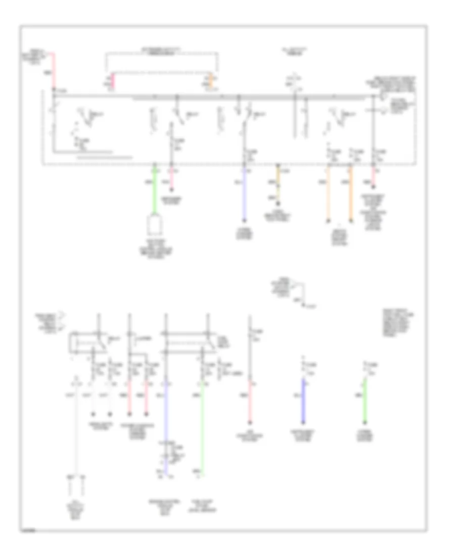
Power Distribution Wiring Diagram (4 of 4) for Mercedes-Benz ML500 2005
List of elements for Power Distribution Wiring Diagram (4 of 4) for Mercedes-Benz ML500 2005:
- (below right side of dash, behind kick panel) right front footwell fuse & relay box
- A12 c4
- A8 c3
- Aac push- button control module (behind center of dash)
- Air conditioning system
- All activity module
- All activity module (in "e" box)
- B12
- C/d
- Defogger system
- Engine control module (in "e" box)
- Extended activity module (eam)
- From battery a (diagram 1 of 4)
- From seat l comfort relay (diagram m 4 of 4)
- From starter switch (diagram 2 of 4)
- Fuel pump & fuel level sensor
- Fuel pump relay
- Fuse & relay box
- Fuse (not used)
- Fuse 15a
- Fuse 20a
- Fuse 25a
- Fuse 30a
- Fuse 35a
- Fuse 40a
- Fuse 7.5a
- Fuse 70a
- Headlights system
- Instrument cluster system
- Instrument cluster system, air conditioning system, interior lights system
- Jumper
- P/d
- Pnk
- Power windows system, mirrors system
- Red
- Relay
- Right front footwell fuse & relay box (below right side of dash, behind kick panel)
- Seats system, memory system
- To high beam relay (diagram 4 of 4)
- W29/2 (behind right kick panel)
- Wiper/ washer system
- X12/6
- X12/7
- X12/9