POWER DISTRIBUTION
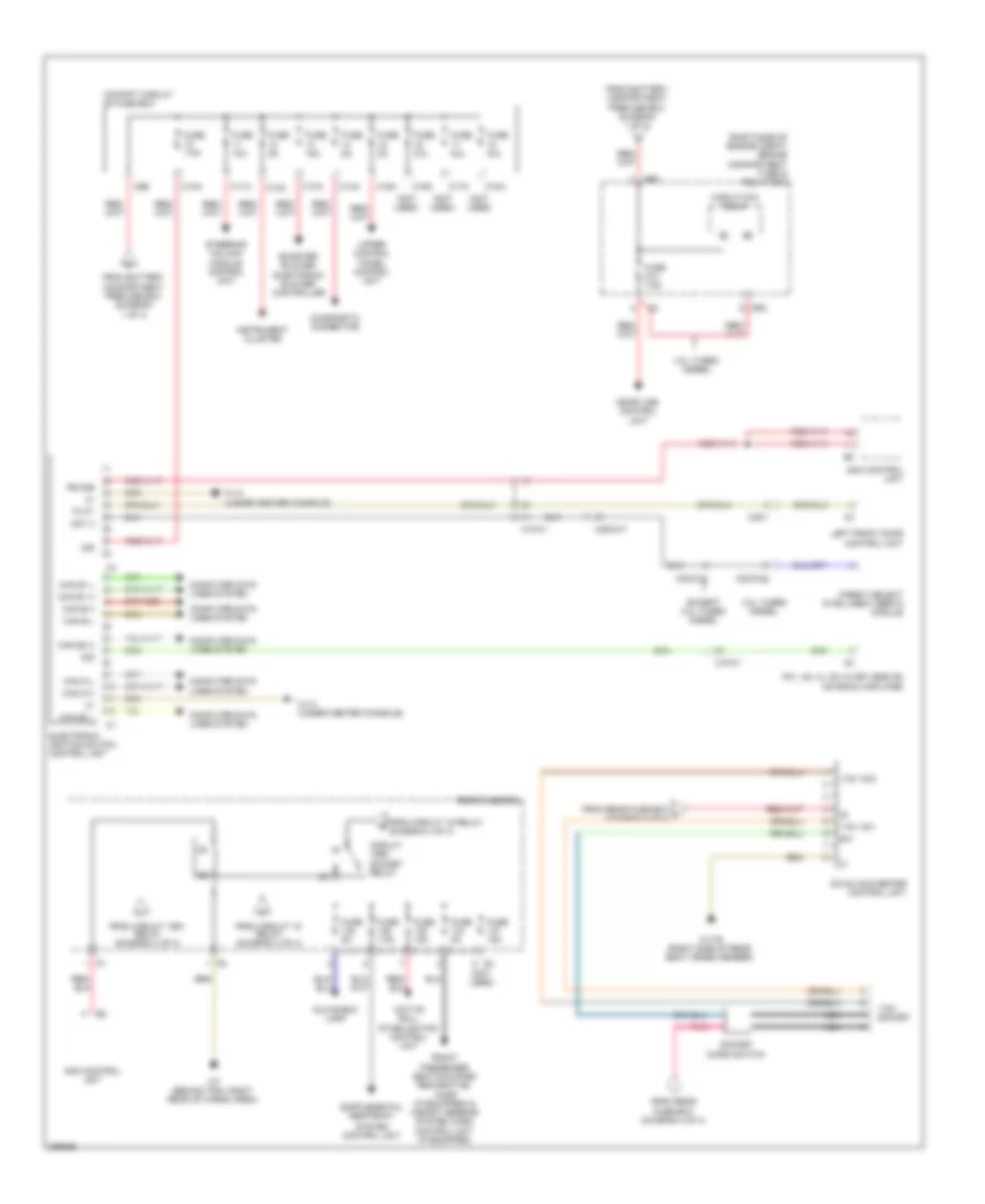
Power Distribution Wiring Diagram (1 of 4) for Mercedes-Benz ML550 2012

List of elements for Power Distribution Wiring Diagram (1 of 4) for Mercedes-Benz ML550 2012:
- (if equipped)
- (not used)
- (under right front seat) battery compartment prefuse box
- 85a
- 85b
- 86a
- 86b
- Ac housing
- Airmatic control unit
- Ata (edw)/ towing sensor/ interior motion sensor control unit
- Audio/ command control panel
- Battery sensor
- C4 red
- Circuit 30g relay
- E2b
- Eco start/ stop function diode (if equipped)
- Eco start/stop function diode (if equipped)
- Electric parking brake control unit
- Electrical power steering control unit
- Electronic stability program control unit
- Emergency call system control (if equipped)
- Engine compartment prefuse box
- Fan motor
- Fm1, am, cl (zv) & keyless go antenna amplifier
- Fuse 100a
- Fuse 10a
- Fuse 125a
- Fuse 150a
- Fuse 15a
- Fuse 200a
- Fuse 25a
- Fuse 30a
- Fuse 400a
- Fuse 40a
- Fuse 5a
- Fuse 7.5a
- Fuse n/a
- Fuse pyro fuse n/a
- Interior prefuse box
- K88
- Keyless go control unit (if equipped)
- Left front door control unit
- Left front reversible emergency tensioning retractor
- Left rear door control unit
- Lower control panel control unit & (w/ on-road/ off-road package & airmatic) off road operating panel control unit (w/ on-road/ off-road package)
- Mf1
- Multiple fuse 1
- On-board electrical system battery
- Overhead control panel control unit
- Panoramic sliding roof control module (w/ panoramic sliding roof) sliding roof control module (w/ glass electric sliding roof)
- Parking system control unit (if equipped)
- Ptc heater booster (if equipped)
- Rear air conditioning electronic blower controller (if equipped)
- Rear control unit
- Red
- Right front door control unit
- Right rear door control unit
- S10
- S12
- S13
- S14
- S15
- S16
- S18
- S22
- Sam control unit
- Sound system amplifier control unit (sound system)
- Sound system amplifier control unit (w/ sound system)
- To cockpit circuit 30 fuse box (diagram 2 of 4)
- To cockpit circuit 30g fuse box (diagram 4 of 4)
- To engine compartment fuse & relay box (diagram 2 of 4)
- To engine compartment fuse & relay box (diagram 3 of 4)
- To multiple fuse 2 (diagram 3 of 4)
- To rear fuse box (diagram 3 of 4)
- To rear fuse box (diagram 4 of 4)
- Transfer case control unit (on-road/ off-road package)
- X18-c2
- X25/2-c2
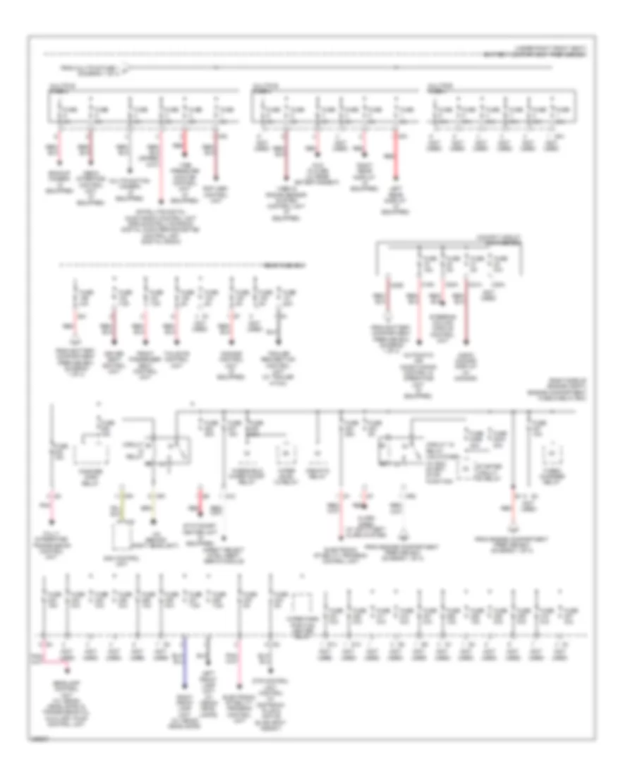
Power Distribution Wiring Diagram (2 of 4) for Mercedes-Benz ML550 2012
List of elements for Power Distribution Wiring Diagram (2 of 4) for Mercedes-Benz ML550 2012:
- (not used)
- (right side of engine compt) engine compartment fuse & relay box
- 115v ac1
- 115v ac2
- 115v socket
- 3.0l turbo diesel
- 30z
- Active roll stabilization control unit
- Booster blower electronic blower controller
- C10a
- C11a
- C12a
- C13a
- C14a
- C15a
- C16a
- C17a
- C18a
- C5e
- Can b h
- Can b l
- Can d h
- Can d l
- Can e1 h
- Can e1 l
- Can e2 h
- Can e2 l
- Circuit 15r2 socket relay
- Circuit 87m relay
- Cockpit circuit 30 fuse box
- Computer data lines system
- Dc/ac converter control unit
- Diagnostic connector
- Direct select intelligent servo module
- Electronic ignition switch control unit
- Except 3.0l turbo diesel
- Fm1, am, cl (zv) & keyless go antenna amplifier
- From battery compartment prefuse box (diagram 1 of 4)
- From circuit 15 relay (diagram 4 of 4)
- From circuit 15r1 relay (diagram 4 of 4)
- From rear fuse box (diagram 4 0f 4)
- From rear fuse box j (diagram 4 0f 4)
- Front passenger seat occupied recognition, acsr (if equipped) & weight sensing system (wss) control unit (if equipped)
- Fuse 10a
- Fuse 15a
- Fuse 5a
- Fuse 7.5a
- Fuse n/a
- Glove box lamp
- Instrument cluster
- Left front door control unit
- Me-sfi (me) control unit
- Mr2
- Nca
- Not 2
- Pb 30b
- Pnk
- Rear fuse box
- Sam control unit
- Socket micro switch
- Steering column module control unit
- System control unit
- Tk ft
- Upper control panel control unit
- W1/4 (under center console)
- W17/6 (right side of rear seat cross member)
- W7 (behind trim, right rear of cargo area)
- X18-c1
- X22/2-c1
- X22/2-c2
- X25/2-c1
- X35/1
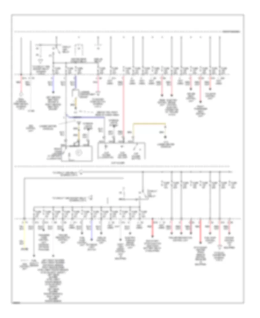
Power Distribution Wiring Diagram (3 of 4) for Mercedes-Benz ML550 2012
List of elements for Power Distribution Wiring Diagram (3 of 4) for Mercedes-Benz ML550 2012:
- (not used)
- (right side of engine compt) engine compartment fuse & relay box
- (under right front seat) battery compartment prefuse box
- (w/ eco start/ stop function)
- Airmatic relay
- Alarm siren (w/ anti-theft alarm system)
- Audio/ comand display (w/ comand)
- Automatic air conditioning control & operating unit (if equipped)
- Backup camera (if equipped)
- C19a
- C20a
- C20e
- C21a
- C22a
- Circuit
- Circuit 15 relay (unlatched)
- Cockpit circuit 30g fuse box
- Comand control unit (if equipped)
- Direct select intelligent servo module
- Driver seat control unit
- Dtr control unit control (w/ distronic plus & active blind spot assist)
- Dvd player (w/ rear entertainment)
- Electronic stability program control unit
- Fanfare horn relay
- From battery compartment prefuse box (diagram 1 of 4)
- From engine compartment prefuse box (diagram 1 of 4)
- From multiple fuse 1 c (diagram 1 of 4)
- Front passenger seat control unit
- Fully integrated transmission control unit
- Fuse 10a
- Fuse 15a
- Fuse 20a
- Fuse 240a 30a
- Fuse 240b 30a
- Fuse 25a
- Fuse 30a
- Fuse 5a
- Fuse 7.5a
- Fuse n/a
- Headlamp control unit (w/ xenon headlamps) & transmission oil auxiliary pump control unit
- Left front lamp unit (w/ xenon head- lamps)
- Left rear display (if equipped)
- Media interface control unit (if equipped)
- Mf2
- Mf3
- Mf4
- Mr1
- Mr2
- Multifunction camera (if equipped)
- Multiple fuse 2
- Multiple fuse 3
- Multiple fuse 4
- Pnk
- Rcp (hbf) control unit
- Rear fuse box
- Red
- Relay
- Right front lamp unit (w/ xenon headlamps)
- Right rear display (if equipped)
- S12
- S13
- S14
- S21
- Sam control unit
- Satellite digital audio radio control unit (sirius satellite radio) digital audio broadcasting control unit (digital radio)
- Starter circuit 50 relay
- Stationary heater unit (if equipped)
- Steering column module control unit
- Tailgate control unit
- Tire pressure monitor control unit (if equipped)
- Trailer recognition control unit (w/ trailer hitch)
- Turbo- charger relay
- Uh2
- Video & radar sensor system control unit (if equipped)
- W2 (behind right headlight)
- Windshield wiper on/off relay
- Wiper level 1/2 relay
- Wiper park position heater relay
Power Distribution Wiring Diagram (4 of 4) for Mercedes-Benz ML550 2012
List of elements for Power Distribution Wiring Diagram (4 of 4) for Mercedes-Benz ML550 2012:
- (behind trim, right rear of cargo area)
- (not used)
- (under center console)
- Circuit 15r1 relay
- Circuit relay
- Comand control unit (if equipped)
- Cup holder
- Cup holder button
- Cup holder illumination
- Cup holder ind lamp
- Driver seat control unit
- E1a
- E1b
- Eco start/ stop function additional battery relay (if equipped)
- Electric brake control electric connector (w/ trailer hitch)
- Electric parking brake control unit
- Exterior light switch
- From interior prefuse box (diagram 1 of 4)
- Front cigar lighter w/ ashtray illumination
- Front passenger seat control unit
- Fuel pump control unit
- Fuel quality sensor
- Fuse 10a
- Fuse 15a
- Fuse 20a
- Fuse 25a
- Fuse 30a
- Fuse 40a
- Fuse 5a
- Fuse 7.5a
- Fuse n/a
- Heated rear window relay
- Interior lights system
- Left front bumper/ right front bumper/ distronic sensor, right rear bumper intelligent radar sensor (w/ blind spot assist), left rear bumper intelligent radar sensor (w/ blind spot assist), left rear bumper radar sensor & right rear bumper radar sensor
- Left second seat row socket & right second seat row socket
- Luggage compartment socket
- Nca
- Night view assist control unit (if equipped)
- Pnk
- Rear control unit
- Rear fuse box
- Red
- S10
- S11
- S12
- S13
- S14
- S18
- S19
- S20
- Sam control unit
- Stationary heater radio remote control reciever (if equipped)
- Tailgate control unit
- To circuit 15r2 relay (diagram 2 of 4)
- To circuit 15r2 socket relay (diagram 2 of 4)
- To dc/ac converter (diagram 4 of 4)
- To socket micro switch (diagram 4 of 4)
- Trailer recognition control unit
- Transfer case control unit (on-road/ off road package)
- W12
- W12 (under center console)
- X29/6-c1