POWER DISTRIBUTION
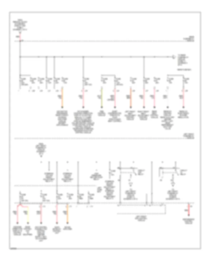
Power Distribution Wiring Diagram (1 of 4) for Mercedes-Benz S500 2005

List of elements for Power Distribution Wiring Diagram (1 of 4) for Mercedes-Benz S500 2005:
- A/c system blower unit
- Air pump relay
- Air suspension relay
- Airmatic w/ ads control module
- Battery
- Engine electronic/ chassis relay
- Engine/ climate control electric cooling fan
- Fanfare relay
- Fuse (res or 30a)
- Fuse (res)
- Fuse 100a
- Fuse 150a
- Fuse 15a
- Fuse 20a
- Fuse 30a
- Fuse 40a
- Fuse 5a
- Fuse 60a
- Generator
- L16
- L19
- L21
- L22
- Left front door control module
- Left front fuse/relay module
- Left fuse box
- Mr1
- Red
- Right front door control module
- Right front fuse/relay module
- Right front sam control module
- Right fuse box
- Starter
- Steering column longitudinal adjustment relay 1
- Steering column longitudinal adjustment relay 1, steering column longitudinal adjustment relay 2
- Steering column longitudinal adjustment relay 2
- Terminal block & fuse box (circuit 30 & 61)
- Terminal block & fuse box (circuit 30z)
- To cockpit fuse box (fuse 78) (diagram 4 of 4)
- To cockpit fuse box (fuse 80) (diagram 4 of 4)
- To electronic ignition- starter control module (diagram 4 of 4)
- To left front fuse/relay module (fuse 23) (diagram 2 of 4)
- To rear fuse/relay module (fuse 55) (diagram 2 of 4)
- W10 (right rear side of trunk)
- Windshield heater relay
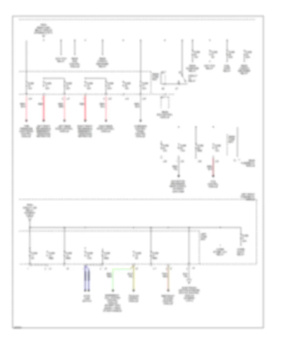
Power Distribution Wiring Diagram (2 of 4) for Mercedes-Benz S500 2005
List of elements for Power Distribution Wiring Diagram (2 of 4) for Mercedes-Benz S500 2005:
- (or 15a)
- (or 7.5a)
- Audio gateway control unit
- Cd changer, command operating display & control module, tv tuner, tele aid control module, emergency called control module voice control system control module, telephone interface, telecommunication control module
- Circuit 15r relay
- Circuit relay
- Command operating display & control module,
- E-net compensator, pneumatic pump (for dynamic seat control)
- Esp/sps/bas control module
- From left front fuse/relay module (diagram 1 of 4)
- From terminal block & fuse box (circuit 30z) fuse 2 (diagram 1 of 4)
- Fuse 10a
- Fuse 15a
- Fuse 15a (or 7.5a)
- Fuse 20a
- Fuse 25a
- Fuse 30a
- Fuse 30a (or 25a)
- Fuse 5a
- Fuse 7.5a
- Fuse 7.5a (or 30a)
- Fuse res
- High pressure return pump relay
- L12
- L13
- L14
- L29
- L30
- L31
- L32
- L33
- L34
- L35
- L37
- L38
- L39
- Left front fuse/relay module
- Left front sam control module
- Left front seat adjustment control module
- Left fuse box
- Navigation processor, rear window antenna amplifier module (except 2003 models)
- Pse control module
- Rear a/c electronic blower regulator,
- Rear fuse box
- Rear fuse/relay module
- Rear seat control module
- Red
- Right front seat adjustment control module
- Sdar control unit (if equipped)
- Sound amplifier
- Steering column height adjustment relay 1, steering column height adjustment relay 2
- Steering column height adjustment relay 2
- To left front fuse/relay module (fuse 11) (diagram 3 of 4)
- To left front fuse/relay module (fuse 6) (diagram 4 of 4)
- To rear fuse/relay module (fuse 71) (diagram 3 of 4)
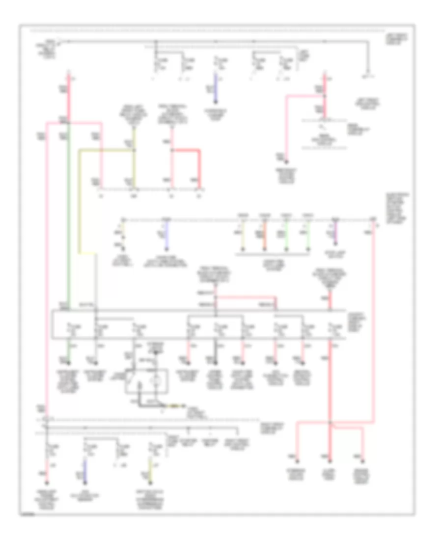
Power Distribution Wiring Diagram (3 of 4) for Mercedes-Benz S500 2005
List of elements for Power Distribution Wiring Diagram (3 of 4) for Mercedes-Benz S500 2005:
- Anti-tow relay
- Circuit relay
- Electronic ignition-starter switch control module (diagram 4 of 4)
- Emergency call system control module (except 2003 & early prod of 2004 models)
- From circuit 15r relay (diagram 2 of 4)
- From rear fuse/ relay module (diagram 2 of 4)
- Fuel pump relay
- Fuse 10a
- Fuse 15a
- Fuse 30a
- Fuse 40a
- Fuse 5a
- Fuse 7.5a
- Fuse res
- L11
- L28
- L33
- L36
- L40
- L41
- L42
- L43
- L44
- L45
- Left front fuse/relay module
- Left front reversible emergency tensioning retractor
- Left fuse box
- Left rear door control module
- Navigation processor, rear window antenna amplifier
- Overhead control panel control module
- Pts control module
- Rear fuse box
- Rear fuse/relay module
- Rear sam control module
- Rear sunshade relay
- Rear window defogger relay
- Red
- Restraint system control module
- Right front reversible emergency tensioning retractor
- Right rear door control module
- Stop lamp switch
- Tele-aid control module
- Tire pressure monitoring control module
- Wiper in/out relay
- Wiper stage 1 & 2 relay
Power Distribution Wiring Diagram (4 of 4) for Mercedes-Benz S500 2005
List of elements for Power Distribution Wiring Diagram (4 of 4) for Mercedes-Benz S500 2005:
- 15r
- 30z
- 78a
- 79a
- 80a
- 81a
- 82a
- 83a
- 84a
- 85a
- 86a
- Aac multifunction sensor
- Acc pushbutton control module
- Alarm signal horn
- Bls
- Can-b h
- Can-b l
- Can-c h
- Can-c l
- Central gateway control module
- Cigar lighter
- Cockpit fuse box (right side of dash)
- Computer data lines system
- Computer data lines system (data link connector)
- Diag
- Electronic ignition- starter switch control module (left side of dash)
- Engine control module (me-sfi)
- Fanfare relay
- From e circuit 15 relay (diagram 2 of 4)
- From left front fuse/ relay module (diagram 3 of 4)
- From terminal block & fuse box (circuit 30 & 61) (diagram 1 of 4)
- From terminal block & fuse box (circuit 30z) (diagram 1 of 4)
- Fuse 10a
- Fuse 15a
- Fuse 5a
- Fuse 7.5a
- Fuse res
- Headlamp range adjustment control module
- Ignition coils, radio interference suppression capacitors
- Instrument cluster system
- Instrument cluster system, computer data lines system
- Interior lights system
- L10
- L20
- L26
- L27
- Left front fuse/relay module
- Left front sam control module
- Left fuse box
- Nca
- Pnk/ red
- Rear fuse/relay module
- Rear sam control module
- Red
- Restraint system control module
- Right front fuse/relay module
- Right front sam control module
- Right fuse box
- Starter relay
- Steering column module
- Stop lamp switch
- Upper control panel control module
- W36/2 (at right footwell)
- Windshield washer pump