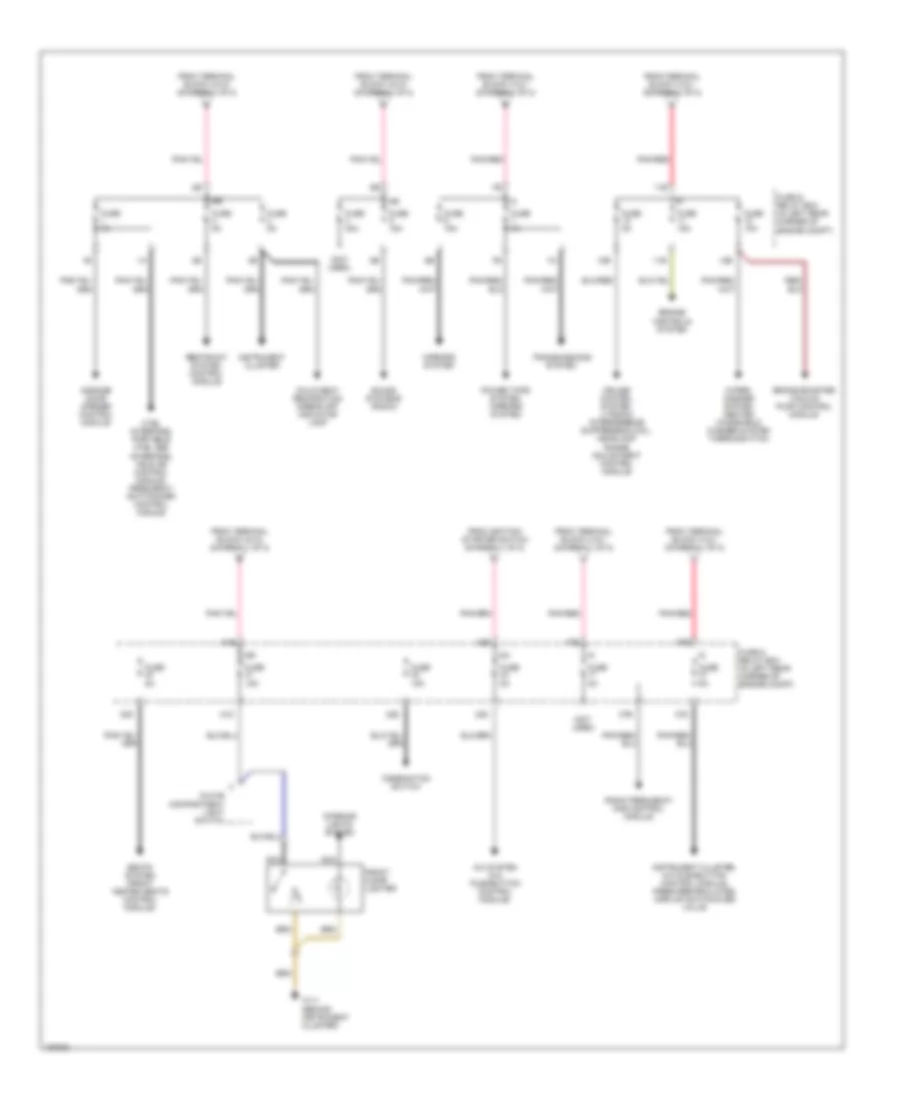
POWER DISTRIBUTION
Power Distribution Wiring Diagram (1 of 2) for Mercedes-Benz SLK320 2001

List of elements for Power Distribution Wiring Diagram (1 of 2) for Mercedes-Benz SLK320 2001:
- (in left rear corner of engine compt) fuse & relay box
- (left rear of eng compt) terminal block x4
- 13a
- 13b
- 13e
- 14b
- 14e
- 15b
- 15e
- 15r
- 15x
- 16b
- 16e
- 19b
- 19e
- 20b
- 23a
- 24b
- 24e
- 25b
- 34d
- 35d
- 35e
- 36d
- Accy
- Alarm siren with auxiliary battery, ata tow sensor, tele aid control module, voice activation control module
- Battery
- Battery fuse box (on right side of engine compt, forward of battery)
- Brake booster vacuum pump control module
- Cockpit switch group, locking confirmation relay module, instrument cluster, warning buzzer contact, a/c pushbutton control module, radio frequency das control module
- Combination control module
- Ctel interface
- Ctel interface, tele aid control module
- Diagnostic test connector, steering angle sensor
- Duovalve, coolant circulation pump
- Engine-a/c cooling fan control module
- Engine/ climate control electric cooling fan control module
- Esp/sps/bas control module, asr/sps control module
- From terminal block x4 (diagram 1 of 2)
- Front dome lamp, combination control module, trunk lamp
- Fuel pump relay, motor 87 relay, electronic traction systems relay
- Fuse 10a
- Fuse 125a
- Fuse 15a
- Fuse 200a
- Fuse 20a
- Fuse 25a
- Fuse 30a
- Fuse 40a
- Fuse 50a
- Fuse 5a
- Generator (2.3l)
- Generator (3.2l)
- Heater system air recirculation unit
- Ignition/ starter switch
- Illumination control module
- Me-sfi control module, pulse module
- Motor 87 relay, electronic traction systems relay
- Nca
- Off
- Pnk/red
- Portable ctel d2b interface, portable ctel antenna amplifier
- Pse control module
- Pulse module
- Red
- Relay module
- Retractable hardtop hydraulic unit
- Run
- Seats system (front heated seats control module)
- Sound system amplifier
- Sound systems (radio)
- Start
- Starter
- Steering angle sensor
- Terminal block x12/1 (left rear of engine compt)
- Terminal block x4/18 (left rear of engine compt)
- To fuse (diagram 2 of 2)
- To fuse 33 (diagram 2 of 2)
- To fuses 1, 2, & 3 (diagram 2 of 2)
- To fuses 10, 11, & 12 (diagram 2 of 2)
- To fuses 30, 31, & 32 (diagram 2 of 2)
- To fuses 4 & 5 (diagram 2 of 2)
- To fuses 6 & 7 (diagram 2 of 2)
- To ignition/ starter switch (diagram 1 of 2)
- Transmission range recognition switch
- W16 (right component compartment)
Power Distribution Wiring Diagram (2 of 2) for Mercedes-Benz SLK320 2001
List of elements for Power Distribution Wiring Diagram (2 of 2) for Mercedes-Benz SLK320 2001:
- (not used)
- 10b
- 11b
- 11e
- 12b
- 15r
- 15x
- 17e
- 30d
- 31d
- 31e
- 32d
- 33d
- 33e
- 37b
- 37d
- 37e
- A/c system (a/c pushbutton control module)
- Brake booster vacuum pump control module
- Child seat recognition airbag off indicator lamp
- Combination switch
- Cruise control system, litronic interference suppression coil, headlamp range adjustment control module
- Ctel interface, portable ctel d2b interface, tele aid control module, frequency switchover control module
- Engine controls system
- From ignition/ starter switch (diagram 1 of 2)
- From terminal block x12/1 (diagram 1 of 2)
- From terminal block x4/18 (diagram 1 of 2)
- Front cigar lighter
- Fuse & relay box (in left rear corner of engine compt)
- Fuse 10a
- Fuse 15a
- Fuse 30a
- Fuse 5a
- G g
- Garage door opener control module
- Glove compartment light switch
- Instrument cluster
- Instrument cluster, a/c pushbutton control module, fresh/recirculated airflap switchover valve
- Interior lights system
- Mirrors system
- Nca
- Pnk/red
- Power tops system, mirrors system
- Radio frequency das control module
- Restraint system control module
- Seats system (front heated seats control module)
- Sound systems (radio)
- Transmissions system
- W1/1 (behind instrument cluster)
- Wiper/ washer system (heated windshield washer system thermoswitch)