POWER DISTRIBUTION
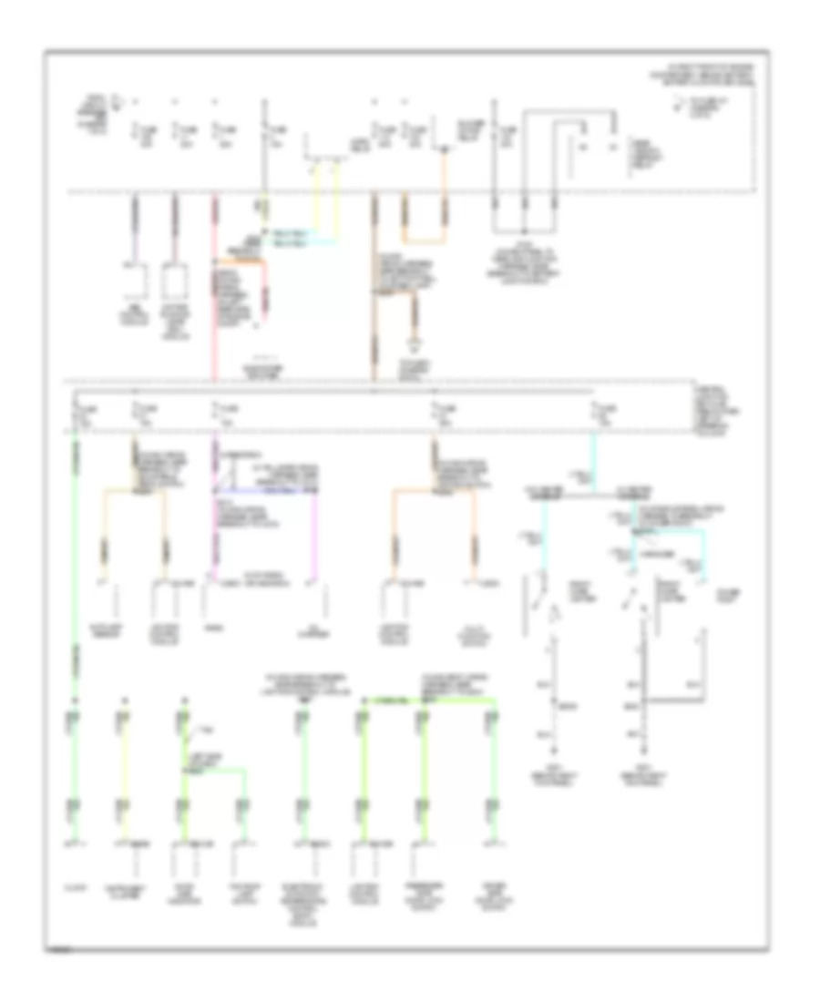
Power Distribution Wiring Diagram (1 of 5) for Mercury Marauder 2003

List of elements for Power Distribution Wiring Diagram (1 of 5) for Mercury Marauder 2003:
- (in main boby wiring harness, near breakout to g204) s245
- (in main body wiring harness, near breakout to c214) s206
- (in main wiring harness, on left rear side of engine compartment)
- (in main wiring harness, on left rear side of engine compt)
- (in police auxiliary junction box wiring harness, near breakout to c423) s425
- (in police auxiliary junction box wiring harness, near breakout to c423) s451
- (in police auxiliary junction box wiring harness, near breakout to c423) s452
- (in right front of engine compartment, behind battery) battery junction box (bjb)
- (near breakout to c146) s152
- Adjustable pedal switch
- Air suspension compressor relay
- Air suspension module
- Battery
- Battery junction box (bjb) (in right front of engine compt, behind battery)
- Bkl/
- C2131b
- C2220a
- C2231b
- C2232a
- C2232b
- C2232d
- C4170c
- C4170d
- C4170e
- C4170f
- C501c
- Circuit breaker 20a
- Driver door module
- Driver side door lock switch
- Driver side front seat adjust switch
- Ends in b-pillar harness
- Ends in harness
- Engine cooling fan motor
- Except marauder
- From a fuse 6 (diagram 1 of 5)
- Front police auxiliary junction box (crown victoria with police package) (behind center of dash)
- Fuel door release switch
- Fuse 20a
- Fuse 25a
- Fuse 30a
- Fuse 50a
- Generator
- Instrument cluster
- Left front lumbar adjust switch
- Luggage compartment lid release switch 1
- Luggage compartment lid release switch 2
- Marauder
- Nca
- Passenger side door lock switch
- Passenger side front seat adjust switch
- Police
- Police power relay
- Rear police auxiliary junction box (crown victoria with police package) (behind bottom center of rear seats)
- Red
- Right front lumbar adjust switch
- Roof opening panel relay
- S100 (in dash panel to headlamp junction harness, near breakout to g102)
- S114 (in starter motor relay & battery ground harness, near breakout to c146)
- S2011
- S2013
- S250 (in main wiring harness, near breakout to lighting control module)
- S289
- Starter motor
- Tan
- To fuse 106 (diagram 2 of 5)
- To fuse 114 (diagram 1 of 5)
- Variable assist power steering (vaps) module
- W/ air suspension
- W/ variable assist power steering (vaps) module
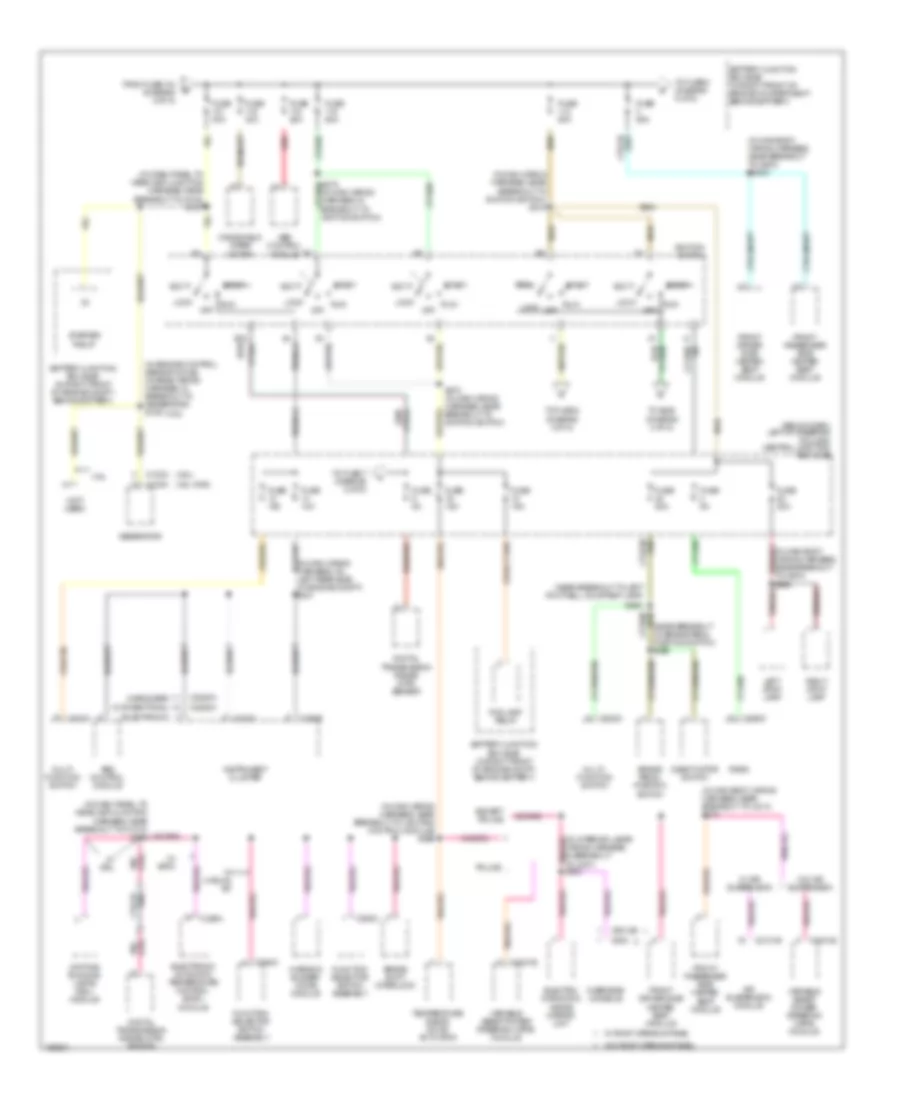
Power Distribution Wiring Diagram (2 of 5) for Mercury Marauder 2003
List of elements for Power Distribution Wiring Diagram (2 of 5) for Mercury Marauder 2003:
- (behind right kick panel)
- (in console panel wiring harness, in breakout to power point) s249
- (in main body wiring harness, near breakout to g204) s228
- (in main wiring harness, near breakout to lighting control module) s227
- (in main wiring harness, near breakout to adjustable pedal switch) s285
- (in main wiring harness, near breakout to ignition switch) s262
- (in main wiring harness, near breakout to left footwell courtesy lamp) s239
- (in right front of engine compartment, behind battery) battery junction box (bjb)
- (in taillamps wiring harness, near breakout to c410) s410
- (left side of dash) s282
- (m100 radio) (apline radio)
- Abs control module
- Alpine radio
- Autolamp sensor
- Blower motor relay
- C202c
- C2145b
- C220b
- C2212b
- C228a
- C290c
- Cd changer
- Central junction box (cjb) (below dash, left of steering column)
- Clock
- Daytime running lamps (drl) module
- Door ajar indicator
- Driver side door lock switch
- Electronic automatic temperature control (eatc) module
- From circuit breaker (diagram 1 of 5)
- Front cigar lighter
- Fuse 15a
- Fuse 20a
- Fuse 25a
- Fuse 40a
- Fuse 50a
- G201
- Horn relay
- Instrument cluster
- Lighting control module
- Marauder
- Multi- function switch
- Passenger side door lock switch
- Power point
- Radio
- Rear window defrost relay
- S104 (near breakout to g102)
- S153 (in dash panel to headlamp junction harness, near breakout to battery junction box)
- S2006
- S213 (in main wiring harness, near breakout to c275)
- S248
- Subwoofer amplifier
- Taxi
- Taxi roof lamp switch
- To fuse 101 (diagram 3 of 5)
- To fuse 3 (diagram 5 of 5)
- W/ center console
- W/o center console
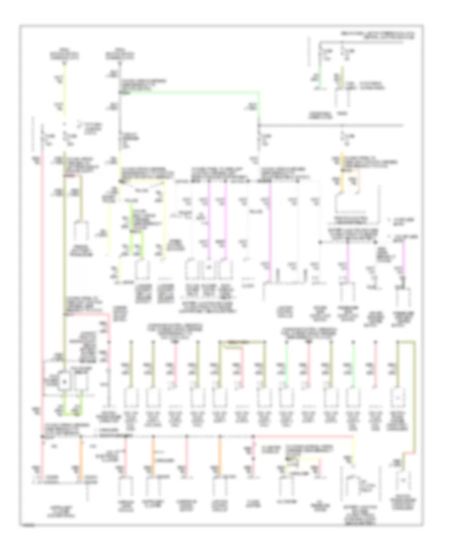
Power Distribution Wiring Diagram (3 of 5) for Mercury Marauder 2003
List of elements for Power Distribution Wiring Diagram (3 of 5) for Mercury Marauder 2003:
- (4.6l cng)
- (4.6l)
- (below dash, left of steering column) central junction box (cjb)
- (conventional)
- (electronic)
- (in dash panel to headlamp junction harness, near breakout to g102) s127
- (in engine control sensor & fuel charge wiring harness, in breakout to generator) s106
- (in main body wiring harness, near breakout to c214) s274
- (in main body wiring harness, near breakout to g200) s2003
- (in main wiring harness, near breakout to ignition switch) s219
- (in main wiring harness, near breakout to lighting control module) s266
- (in main wiring harness, on left rear side of engine compt) s231
- (marauder)
- (near breakout to brake pedal position switch) s265
- (near breakout to left footwell courtesy lamp)
- (not used)
- 4.6l
- Abs control module
- Acc
- Air suspension module
- Battery junction box (bjb) (in right front of engine compartment, behind battery)
- Battery junction box (bjb) (in right front of engine compt, behind battery)
- Brake pedal position switch
- Brake shift interlock
- C102a
- C102c
- C202a
- C2131b
- C220b
- C220c
- C2220a
- C2231b
- C228a
- C290c
- C294c
- C9013b
- C930
- Daytime running lamps (drl) module
- Deactivator switch
- Digital transmission range (dtr) sensor
- Electro- chromatic inside mirror unit
- Electronic automatic temperature control (eatc) module
- Except police
- Fog lamp relay
- From fuse 104 (diagram 2 of 5)
- Front driver side heated seat module
- Front passenger side heated seat module
- Function selector switch assembly
- Fuse 10a
- Fuse 15a
- Fuse 20a
- Fuse 25a
- Fuse 30a
- Fuse 50a
- Fuse 5a
- Generator
- Ignition switch
- Instrument cluster
- Left stop lamp
- Lock
- Multi- function switch
- Off
- Overhead console
- Police
- Radio
- Red
- Red/
- Right stop lamp
- Run
- S263
- S270 (in main wiring harness, near breakout to ignition switch)
- Start
- Starter relay
- Temperature blend door actuator
- To fuse 5 (diagram 5 of 5)
- To fuse 7 (diagram 5 of 5)
- To fuse 8 (diagram 4 of 5)
- To s225 (diagram 4 of 5)
- Variable assist power steering (vaps) module
- W/ air suspension
- W/ drl
- W/ eatc
- W/ manual a/c
- W/ roof opening panel
- W/o air suspension
- W/o roof opening panel
- Warning buzzer/ chime module
- Windshield wiper motor
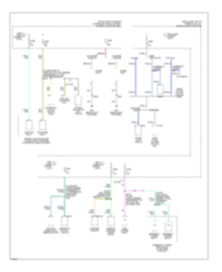
Power Distribution Wiring Diagram (4 of 5) for Mercury Marauder 2003
List of elements for Power Distribution Wiring Diagram (4 of 5) for Mercury Marauder 2003:
- (below dash, left of steering column) central junction box (cjb)
- (in console panel wiring harness, near breakout to c219) s2007
- (in dash panel to headlamp junction harness, near breakout to c1010) s117
- (in engine control sensor & fuel charge wiring harness, near breakout to c1033) s151
- (in engine control sensor & fuel charge wiring harness, near breakout to coil on plug 8) s103
- (in main body wiring harness, near breakout to g204) s218
- (in main wiring harness, near breakout to adjustable pedal switch) s2009
- (in main wiring harness, near breakout to autolamp sensor) s276
- (in main wiring harness, near breakout to function selector switch assembly) s211
- (in main wiring harness, near breakout to ignition switch) s225
- (in right front of engine compt, behind battery) battery junction box (bjb)
- (m100 radio) (alpine radio)
- 4.6l
- 4.6l w/ electronic cluster
- A/c clutch relay
- Battery junction box (bjb) (in right front of engine compartment, behind battery)
- Battery junction box (bjb) (in right front of engine compt, behind battery)
- Blower motor relay
- C2145a
- C2145c
- C2220a
- C2220b
- C240 c290c
- C504b
- Circuit breaker 20a
- Clock
- Coil on plug (cop) 1
- Coil on plug (cop) 2
- Coil on plug (cop) 3 (4.6l cng)
- Coil on plug (cop) 3 (4.6l)
- Coil on plug (cop) 4 (4.6l cng)
- Coil on plug (cop) 4 (4.6l)
- Coil on plug (cop) 5 (4.6l cng)
- Coil on plug (cop) 5 (4.6l)
- Coil on plug (cop) 6 (4.6l cng)
- Coil on plug (cop) 6 (4.6l)
- Coil on plug (cop) 7
- Coil on plug (cop) 8
- Driver side door lock switch
- Driver side seat heated
- Entry
- Except marauder
- Except police
- Floor shifter
- From ignition switch (diagram 3 of 5)
- Fuse 15a
- Fuse 25a
- Fuse 5a
- Fuse 7.5a
- Headlamp junction harness, near breakout to g102) s154
- Ignition trans- former capacitor 1 (marauder)
- Ignition transformer capacitor
- Ignition transformer capacitor 2 (marauder)
- Instrument cluster
- Instrument cluster (conventional)
- Lighting control module
- Luggage compart- ment lid release switch 1
- Luggage compart- ment lid release switch 3
- Marauder
- Master window adjust switch
- Nca
- Oil pressure gauge
- Overdrive cancel switch
- Passenger side door lock switch
- Passenger side seat heated
- Passive anti-theft transceiver
- Pcm power diode
- Pcm power relay
- Police
- Police power relay
- Radio
- Red/ (in main wiring harness, on left rear side of engine compt) s223
- Roof opening panel relay
- S288 (near breakout to g200)
- Speed control actuator
- Switch
- To fuse 4 (diagram 5 of 5)
- Traction control indicator relay
- Voltmeter
- W/ center console
- W/ eatc
- W/ keyless
- W/o keyless
- Warning lamps module
- Windshield wiper motor
Power Distribution Wiring Diagram (5 of 5) for Mercury Marauder 2003
List of elements for Power Distribution Wiring Diagram (5 of 5) for Mercury Marauder 2003:
- (behind right kick panel)
- (below dash, left of
- (diagram 2 of 5)
- (in breakout to radio) s201
- (in dash panel to headlamp junction harness, near breakout to left front brake sensor) s115
- (in main body wiring harness, near breakout to air suspension module) s246
- (in main body wiring harness, near breakout to c213) s2015
- (in main body wiring harness, near breakout to temperature blend door actuator) s229
- (in right front of engine
- 4.6l cng
- Base vehicle, taxi
- Battery junction box (bjb) (in right front of engine compartment, behind battery)
- C2232a
- C310b
- C4170c
- C501a
- C9013b
- Compartment, behind battery) battery junction box (bjb)
- Data link connector (dlc)
- Driver door module
- Emergency flasher relay 1
- Emergency flasher relay 2
- Emergency flasher relay block (in left rear of trunk)
- Entry
- Exterior rear view mirror switch
- From fuse 25 m
- From fuse 3 s (diagram 3 of 5)
- From fuse 8 (diagram 4 of 5)
- From fuse 9 (diagram 3 of 5)
- Front police auxiliary junction box
- Fuel pump relay
- Fuse 10a
- Fuse 20a
- Fuse 25a
- Fuse 30a
- Fuse 7.5a
- G201
- Natural gas vehicle (ngv) module
- Occupant classification sensor module
- Others
- Overhead console
- Pcm power relay
- Police
- Power point
- Powertrain control module (pcm)
- Radio
- Rear flasher relay
- Rear police auxiliary junction box
- Restraints control module
- S2006
- S2012 (in main wiring harness, near breakout to left footwell courtesy lamp)
- S248
- Steering column) central junction box (cjb)
- W/ center console
- W/ keyless
- W/ police
- W/o center console