POWER DISTRIBUTION
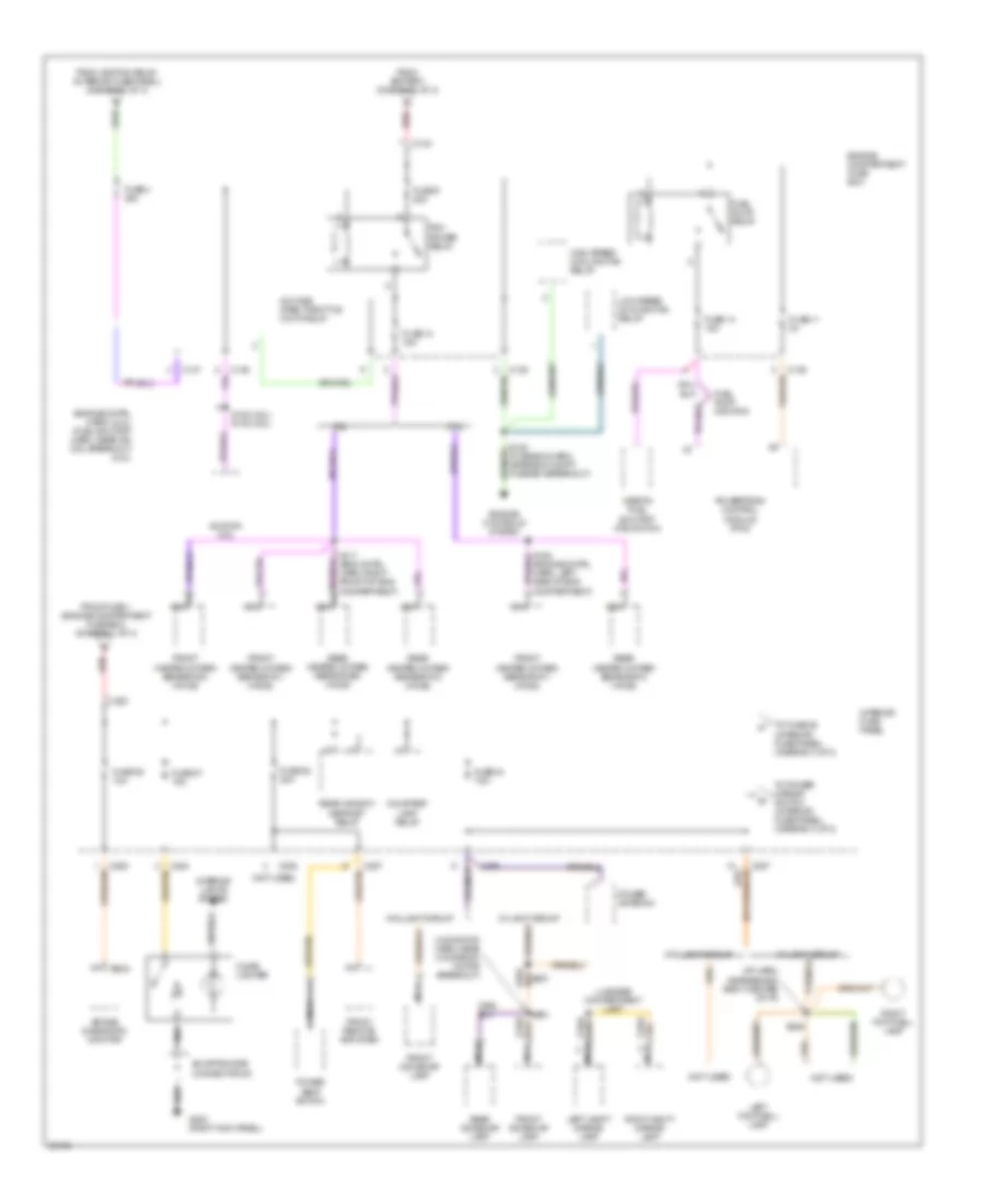
Power Distribution Wiring Diagram (1 of 3) for Mercury Mystique 1997

List of elements for Power Distribution Wiring Diagram (1 of 3) for Mercury Mystique 1997:
- (fuse box harn, above int fuse panel)
- (fuse box harn, in int fuse panel breakout) s205
- (fuse box harn, near abs control module breakout)
- (i/p harn, near inst cluster breakout) s216
- (moonroof harn, center of windshield header)
- (not used)
- 0.200
- A/t
- Abs control module
- Abs hydraulic unit
- Air temperature actuator
- Battery
- Blower motor relay
- C133
- C136
- C137
- C201
- C203
- C205
- C277
- C281
- C282
- C284
- C285
- C288
- C298
- C523
- Circuit breaker 20 10a
- Combination switch
- Combination switch (hazard switch)
- Daytime running lamps (drl) relay
- Engine compartment fuse box
- Fog lamp relay
- From ignition switch diode #2 (interior fuse panel) (diagram 3 of 3)
- Fuse 1 80a
- Fuse 10 20a
- Fuse 10 7.5a
- Fuse 12 15a
- Fuse 2 60a
- Fuse 21 40a
- Fuse 23 15a
- Fuse 3 60a
- Fuse 37 30a
- Fuse 5 15a
- Fuse 7 30a
- Gearshift lever unit
- Generator
- Heater- a/c mode switch
- High beam headlamp relay
- High speed cooling fan relay
- Horn relay
- Ignition relay
- Interior fuse panel
- Interval wiper relay
- Lo beam headlamp relay
- Low speed cooling fan relay
- M/t
- Main light switch
- Master window control switch
- Mega fuse 175a
- Moon- roof switch
- Nca
- One touch down window relay
- Park/neutral position (pnp) switch
- Red
- Resistance wire
- Right front window switch
- S173
- S175 (fuse box harn, near windshield wiper module breakout)
- S201
- S309 (door lock feed harn, near park break switch breakout)
- S503 (left front door lock jumper harn, near left front speaker breakout)
- S902
- Spare
- Speed control module
- Starter motor
- Starter relay
- To fuse 36 (interior fuse panel) (diagram 2 of 3)
- To fuse 4 (engine compartment fuse box) (diagram 2 of 3)
- To fuse 9 (engine compartment fuse box) (diagram 2 of 3)
- To ignition switch (diagram 3 of 3)
- Transmission range (tr) sensor
- W/ drl
- W/ mec iii abs
- W/o mec iii abs
- Windshield wiper motor
- Wiper/ washer switch
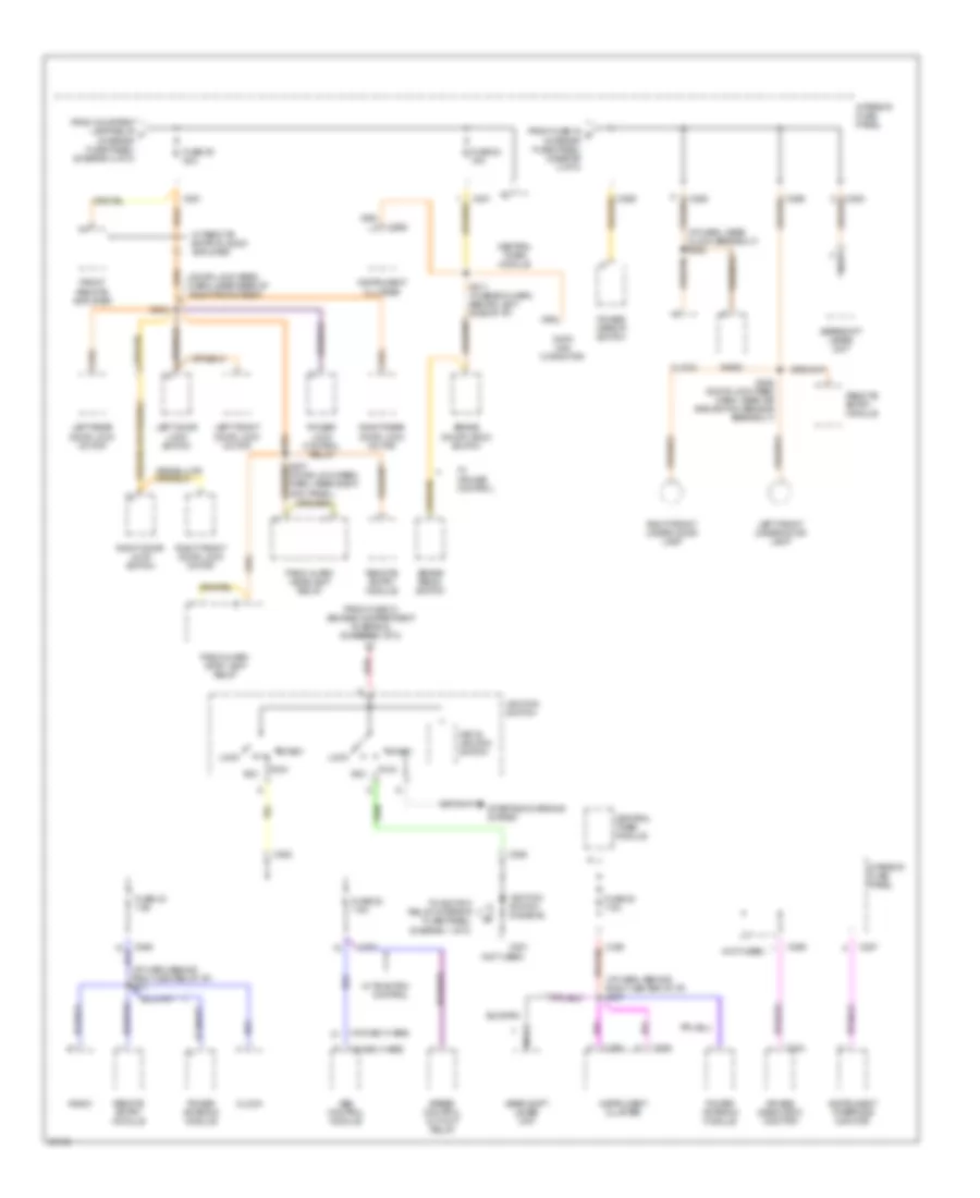
Power Distribution Wiring Diagram (2 of 3) for Mercury Mystique 1997
List of elements for Power Distribution Wiring Diagram (2 of 3) for Mercury Mystique 1997:
- (engine cntrl harn) (2.0l) (fuel shutoff harn, near ign coil breakout) (2.5l)
- (fuse box harn, near eng compt fuse box breakout)
- (i/p harn, near behind right center of i/p)
- (moonfoof harn, near moonroof motor breakout)
- (not used)
- 2.0l
- 2.5l
- A/c wide open throttle (wot) relay
- Air bag diagnostic monitor
- C133
- C136
- C137
- C203
- C205
- C234
- C284
- C285
- C287
- C298
- Cigar lighter
- Courtesy lamp relay
- Engine compartment fuse box
- Engine controls system
- From battery (diagram 1 of 3)
- From fuse 1 (engine compartment fuse box) (diagram 1 of 3)
- From ignition relay (interior fuse panel) (diagram 1 of 3)
- Front dome/map lamp
- Front heated oxygen sensor #11 (ho2s)
- Front heated oxygen sensor #21 (ho2s)
- Front remote amplifier
- Fuel pump monitor
- Fuel pump relay
- Fuse 11 3a
- Fuse 13 15a
- Fuse 14 15a
- Fuse 27 15a
- Fuse 28 30a
- Fuse 34 7.5a
- Fuse 36 10a
- Fuse 4 20a
- Fuse 9 20a
- G203 (right kick panel)
- High speed cooling fan relay
- Ignition coil
- Inertia fuel shutoff (ifs) switch
- Interior fuse panel
- Interior lights system
- Left footwell lamp
- Left vanity mirror lamp
- Low speed cooling fan relay
- Luggage compartment lamp
- Nca
- Pcm power relay
- Power antenna
- Power seat switch
- Powertrain control module (pcm)
- Rear dome/map lamp
- Rear heated oxygen sensor #12 (ho2s)
- Rear heated oxygen sensor #22 (ho2s)
- Rear window defrost relay
- Red
- Right footwell lamp
- Right vanity mirror lamp
- S153 (2.0l) s132 (2.5l)
- S164 (engine cntrl harn, left side of eng compartment)
- S236
- S251
- S904
- Shorting bar connector #3
- To fuse 25 (interior fuse panel) (diagram 3 of 3)
- To power mirror switch (interior fuse panel) (diagram 3 of 3)
- W/o light group
Power Distribution Wiring Diagram (3 of 3) for Mercury Mystique 1997
List of elements for Power Distribution Wiring Diagram (3 of 3) for Mercury Mystique 1997:
- (door lock feed harn, near rear of right front seat)
- (i/p harn, behind right center of i/p) s217
- (i/p harn, behind right center of i/p) s237
- (i/p harn, near clock breakout) s222
- (not used)
- (w/ mec iii abs)
- (w/o mec iii abs)
- Abs control module
- Acc
- Air bag diagnostic monitor
- Brake on/off (boo) switch
- Brake pedal switch
- C201
- C234
- C262
- C281
- C282
- C283
- C285
- C286
- C287
- C288
- C290
- Central timer module
- Clock
- Data link connctor
- From courtesy lamp relay f (interior fuse panel) (diagram 2 of 3)
- From fuse 10 (engine compartment fuse box) (diagram 1 of 3)
- From fuse 34 g (interior fuse panel) (diagram 2 of 3)
- Front remote amplifier
- Fuse 22 7.5a
- Fuse 24 15a
- Fuse 25 20a
- Fuse 30 7.5a
- Fuse 32 7.5a
- Gear shift lever unit
- Gearshift lever unit
- Ignition switch
- Ignition switch diode #2
- Instrument cluster
- Instrument interface monitor
- Interior fuse panel
- Key in ignition switch
- Left door lock switch
- Left front door lock motor
- Left front under door lamp
- Left rear door lock motor
- Lock
- Nca
- Panic alarm headlamp relay
- Panic alarm stop lamp relay
- Power antenna module
- Power lock control relay
- Power mirror switch
- Radio
- Red
- Remote entry module
- Right door lock switch
- Right front door lock motor
- Right front under door lamp
- Right rear door lock motor
- Run
- S207 (door lock feed harn, near right kick panel)
- S208 (door lock feed harn, near air bag switch sensor breakout)
- S211 (fuse box harn, behind left side of i/p)
- S304
- Speed control cut-out relay
- Start
- Starting/charging system
- To ignition relay (interior fuse panel) (diagram 1 of 3)
- W/ cruise control
- W/ remote entry & audi0 amplifier
- W/ traction control