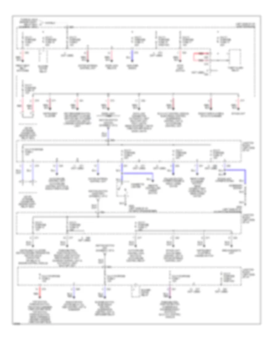
POWER DISTRIBUTION
Power Distribution Wiring Diagram (1 of 2) for Mitsubishi 3000GT Spyder VR-4 1996

List of elements for Power Distribution Wiring Diagram (1 of 2) for Mitsubishi 3000GT Spyder VR-4 1996:
- (a/t-right rear of
- (diagram 2 of 2)
- (m/t-right front of
- (not used)
- A/c relay box (left side of engine compt.)
- Abs hydraulic unit (1995) & abs control unit (1995) or abs valve relay & abs motor relay (1996)
- Acc
- Active aero control unit
- Air conditioning magnetic clutch relay
- Battery
- Condenser fan motor relays
- Dedicated fuse 1 20a
- Dedicated fuse 1o 10a
- Dedicated fuse 2 15a
- Dedicated fuse 3 10a
- Dedicated fuse 4 15a
- Dedicated fuse 5 10a
- Dedicated fuse 6 10a
- Dedicated fuse 7 20a
- Dedicated fuse 8 20a
- Dedicated fuse 9 10a
- Defogger relay (left side of i/p)
- Defogger switch, defogger & engine control module
- Engine compartment relay box (right side of engine compt.)
- Engine compt., on top of transaxle)
- Engine control module, srs diagnosis unit, starter relay & park neutral position switch
- Engine, on transaxle stud)
- Fog light relay
- Fusible link 1 120a
- Fusible link 10 40a
- Fusible link 11 30a
- Fusible link 3 40a
- Fusible link 4 30a
- Fusible link 5 40a
- Fusible link 6 40a
- Fusible link 7 60a
- Fusible link 8 30a
- Fusible link 9 30a
- G119 (m/t)
- G123 (below wiper motor)
- G129 (a/t)
- Generator
- Generator relay & data link connector
- Hazard switch
- Headlight relay
- Headlights
- Horn relay
- Ignition switch
- Instrument cluster
- Interior relay box (left side of i/p)
- Lock
- Mfi relay
- Multi- purpose fuse 6 (junction block)
- Multi-purpose fuse 18 (junction block) (diagram 2 of 2)
- Multi-purpose fuse 3 (junction block) (diagram 2 of 2)
- Multi-purpose fuse 4 (junction block) (diagram 2 of 2)
- Nca
- Overdrive & power/economy switch, heater control panel illumination lights (manual a/c), air conditioning switch, air conditioning control panel (full auto a/c), ecs switch, auto-cruise control main switch, active aero switch, instrument cluster, a/t selector lever illumination, light, fog light switch, front & rear combination lights, license plate lights, inspection light, glove box illumination light, vanity mirrors, hazard switch, cigarette lighter (illumination), ashtray illumination light, radio/tape player & defogger switch
- Power windows relay
- Radiator fan motor
- Red
- Remote controlled mirrors
- Side mirror heaters
- Start
- Starter motor
- Sunroof control unit
- Tail light relay
- Top stack harness (1995 convertible only)
Power Distribution Wiring Diagram (2 of 2) for Mitsubishi 3000GT Spyder VR-4 1996
List of elements for Power Distribution Wiring Diagram (2 of 2) for Mitsubishi 3000GT Spyder VR-4 1996:
- (left side of i/p) junction block
- (not used)
- Accessory socket
- Amplifier (radio)
- Auto-cruise control main switch & auto-cruise control relay
- Auto-cruise control unit, auto-cruise control switch & radio/tape player
- Blower motor relay
- Blower switch, electronic control suspension control unit & defogger relay
- C68
- C69
- C70
- C71
- C74
- C77
- C78
- C80
- C81
- C82
- C83
- Cigarette lighter
- Column switch (wiper/washer) & front wper motor
- Data link connector, automatic light shut-off unit, foot lights, rear courtesy lights (1996 convertible) & door lights
- Dome light (1995)
- Door lock relays
- Elc-4 a/t control module, electronic control suspension control unit & auto-cruise control unit
- Etacs unit
- Etacs unit (wiper system)
- Etacs unit, active aero control unit & motor antenna control unit
- Front seat belt switches
- Fusible link 6 (engine compt. relay box) (diagram 1 of 2)
- G202 (left side of i/p, on deck crossmember)
- Ignition switch (acc/on) (diagram 1 of 2)
- Ignition switch (on) (diagram 1 of 2)
- Ignition switch (on/start) (diagram 1 of 2)
- Instrument cluster
- Instrument cluster & hazard switch
- Instrument cluster, ignition power transistor, ignition coils, capacitor, mfi relay & engine control module
- Iod or storage connector (engine compt. relay box)
- Junction block (left side of i/p)
- Key reminder switch, instrument cluster, ignition key cylinder illumination light & luggage compartment light
- Motor antenna control unit
- Multi- purpose fuse 1 10a
- Multi- purpose fuse 10 15a
- Multi- purpose fuse 11 15a
- Multi- purpose fuse 12 10a
- Multi- purpose fuse 13 20a
- Multi- purpose fuse 14 20a
- Multi- purpose fuse 15 position
- Multi- purpose fuse 16 30a
- Multi- purpose fuse 17 15a
- Multi- purpose fuse 18 10a
- Multi- purpose fuse 19 10a
- Multi- purpose fuse 5 20a
- Multi- purpose fuse 6 15a
- Multi- purpose fuse 8 position
- Multi- purpose fuse 9 20a
- Multi-purpose fuse 2 10a
- Multi-purpose fuse 3 10a
- Multi-purpose fuse 4 10a
- Multi-purpose fuse 7 10a
- Park/neutral position switch, backup light switch, srs diagnostic unit, sunroof control unit & automatic light shut-off unit
- Park/neutral postion switch, overdrive & power/economy switch & elc-4 a/t control module
- Radiator fan motor relay (hi), abs control unit & g-sensor
- Radio/tape player & cd auto changer
- Rear wiper & washer switch, rear intermittent wiper relay & rear wiper motor
- Red
- Remote controlled mirror switch
- Srs diagnostic unit
- Stop light switch
- Theft-alarm relay
- Top switch, parking switch, top stack harness (1995 convertible), top switch, parking switch, rear harness & header harness (1996 convertible)