POWER DISTRIBUTION
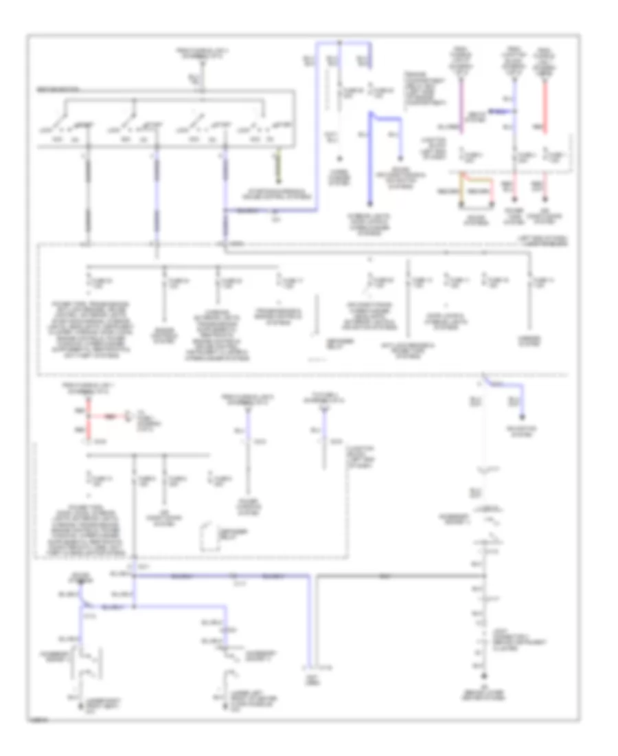
Power Distribution Wiring Diagram (1 of 2) for Mitsubishi Endeavor SE 2010

List of elements for Power Distribution Wiring Diagram (1 of 2) for Mitsubishi Endeavor SE 2010:
- 120a
- Air conditioning & cooling fans systems
- Air conditioning system
- Anti-lock brakes system
- Anti-lock brakes, cruise control, transmissions, exterior lights & anti-theft systems
- Battery
- C31
- Cruise control, engine controls, air conditioning, anti-theft, transmissions & cooling fans systems
- Door locks & exterior lights systems
- Engine compartment relay box (left side of engine compartment)
- Engine controls system
- Exterior lights system
- Front ecu
- Fuse 10 10a
- Fuse 11 15a
- Fuse 12 20a
- Fuse 13 7.5a
- Fuse 14 10a
- Fuse 15 20a
- Fuse 16 10a
- Fuse 17 10a
- Fuse 18 10a
- Fuse 19 10a
- Fuse 20 7.5a
- Fuse 21 7.5a
- Fuse 22 15a
- Fuse 24 15a
- Fuse 6 15a
- Fuse 7 20a
- Fuse 8 15a
- Fuse 9 20a
- Fusible link 1 80a
- Fusible link 2 50a
- Fusible link 26 (positive battery terminal connection)
- Fusible link 27 40a
- Fusible link 3 60a
- Fusible link 4 40a
- Fusible link 5 30a
- Headlight relay high
- Headlight relay low
- Headlights & anti-theft systems
- Headlights system
- Horns, door locks & anti-theft systems
- Off
- Pulse width modulator
- Red
- Seats system
- Starting/ charging system
- Starting/charging system
- Taillight relay
- To fuse 10 (diagram 2 of 2)
- To fuse 3 (diagram 2 of 2)
- To ignition switch (diagram 2 of 2)
- To junction block (diagram 2 of 2)
- Transmissions system
Power Distribution Wiring Diagram (2 of 2) for Mitsubishi Endeavor SE 2010
List of elements for Power Distribution Wiring Diagram (2 of 2) for Mitsubishi Endeavor SE 2010:
- (+)
- (-)
- (left end of dash) junction block
- (not used)
- (under left front of center floor console) g18
- (under right front seat) g14
- Acc
- Accessory socket 2
- Accessory socket 3
- Accessory socket 4
- Air conditioning system
- Air conditioning, wiper/washer, headlights, exterior lights & navigation systems
- Anti-lock brakes & power tops systems
- C112
- C114
- C115
- C116
- C117
- C211
- C212
- C215
- C216
- C24
- C31
- Defogger relay
- Door locks & interior lights systems
- Engine compartment relay box (left side of engine compartment)
- Engine controls system
- From fusible link 1 (diagram 1 of 2)
- From fusible link 1 (diagram 2 of 2)
- From fusible link 27 (diagram 1 of 2)
- From fusible link 4 (diagram 1 of 2)
- From fusible link 5 (diagram 1 of 2)
- From junction block (diagram 2 of 2)
- Fuse 1 7.5a
- Fuse 10 15a
- Fuse 11 15a
- Fuse 13 7.5a
- Fuse 14 7.5a
- Fuse 16 15a
- Fuse 17 7.5a
- Fuse 20 7.5a
- Fuse 22 7.5a
- Fuse 23 10a
- Fuse 23 7.5a
- Fuse 24 10a
- Fuse 25 30a
- Fuse 3 30a
- Fuse 4 20a
- Fuse 5 30a
- Fuse 6 30a
- Fuse 9 15a
- G8 (behind lower center of dash)
- Ignition switch
- Interior lights, door locks & wiper/washer systems
- Joint connector 3 (behind instrument cluster)
- Junction block (left end of dash)
- Lock
- Mirrors system
- Navigation system
- Power tops system
- Power windows system
- Red
- Seats system
- Sound systems
- Sound, air conditioning & navigation systems
- Start
- Starting/charging & cruise control systems
- To fuse 1 (diagram 2 of 2)
- To fuse 4 (diagram 2 of 2)
- Transmissions & engine controls systems
- Wiper/ washer system