POWER DISTRIBUTION
Power Distribution Wiring Diagram (1 of 2) for Mitsubishi Lancer ES 2003

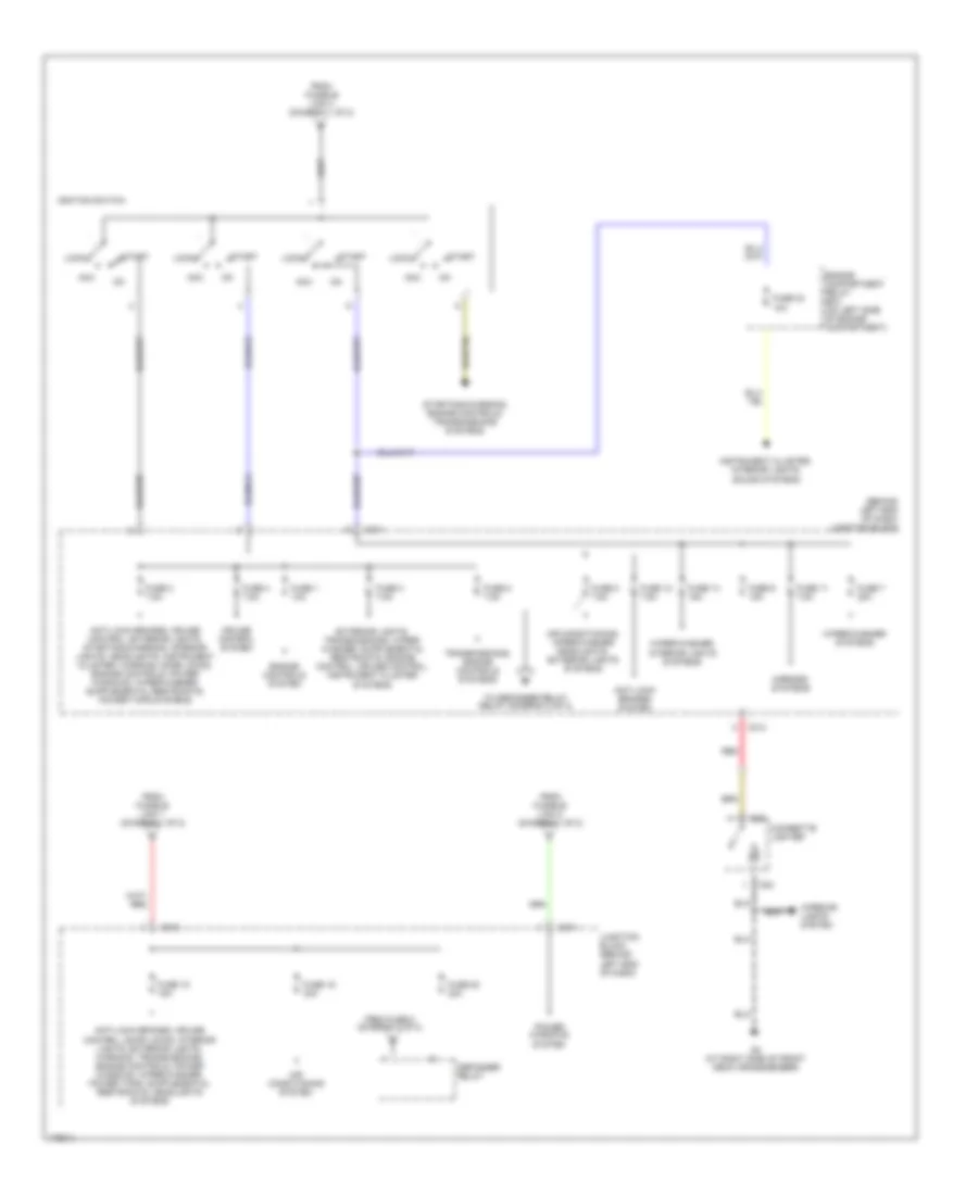
List of elements for Power Distribution Wiring Diagram (1 of 2) for Mitsubishi Lancer ES 2003:
- (connected to battery positive terminal)
- Air conditioning system
- Air conditioning, cooling fans systems
- Air conditioning, sound, interior lights, defogger, transmissions, instrument cluster, exterior lights systems
- Anti-lock brakes system
- Anti-lock brakes, cruise control, transmissions, exterior lights systems
- Battery
- Charging system
- Door locks, exterior lights systems
- Engine compartment relay box (on left side of engine compartment)
- Engine controls system
- Engine controls, transmissions systems
- Exterior lights system
- Exterior lights, instrument cluster, transmissions systems
- Front ecu
- Fuse 10 15a
- Fuse 12 7.5a
- Fuse 13 10a
- Fuse 14 20a
- Fuse 15 15a
- Fuse 16 10a
- Fuse 17 10a
- Fuse 18 10a
- Fuse 19 10a
- Fuse 20 7.5a
- Fuse 21 7.5a
- Fuse 22 10a
- Fuse 25 15a
- Fuse 7 10a
- Fuse 8 20a
- Fuse 9 10a
- Fusible link 1 60a
- Fusible link 2 50a
- Fusible link 26 100a
- Fusible link 3 60a
- Fusible link 4 40a
- Fusible link 5 30a
- G10 (w/o turbo) (at rear of cylinder head) (w/ turbo) (at lower left rear of engine)
- G12 (at left front of engine compt, left of battery)
- Headlight relay high
- Headlight relay low
- Headlights system
- Headlights system (canada)
- Horns systems
- Off
- Pnk
- Red
- Sound, door locks, interior lights, instrument cluster, headlights, warning, power windows, wiper/washer, exterior lights systems
- Starting system
- Starting/ charging system
- Taillight relay
- To fuse 15 (diagram 2 of 2)
- To ignition switch (diagram 2 of 2)
- To junction block (diagram 2 of 2)
- Transmissions system
Power Distribution Wiring Diagram (2 of 2) for Mitsubishi Lancer ES 2003
List of elements for Power Distribution Wiring Diagram (2 of 2) for Mitsubishi Lancer ES 2003:
- (behind left end of dash) junction block
- Acc
- Air conditioning system
- Air conditioning, wiper/washer headlights, exterior lights systems
- Anti-lock brakes system
- C211
- C212
- C214
- Cigarette lighter
- Cruise control system
- D23
- D24
- Defogger relay
- Engine compartment relay box (on left side of engine compartment)
- Engine controls system
- From fuse 5 (diagram 2 of 2)
- From fusible link 1 (diagram 1 of 2)
- From fusible link 4 (diagram 1 of 2)
- From fusible link 5 (diagram 1 of 2)
- Fuse 1 10a
- Fuse 11 7.5a
- Fuse 12 7.5a
- Fuse 14 15a
- Fuse 15 15a
- Fuse 19 30a
- Fuse 2 7.5a
- Fuse 20 30a
- Fuse 23 10a
- Fuse 3 7.5a
- Fuse 4 7.5a
- Fuse 5 7.5a
- Fuse 7 20a
- Fuse 8 7.5a
- Fuse 9 15a
- G3 (at right side of front deck crossmember)
- Ignition switch
- Instrument cluster, interior lights, sound systems
- Interior lights system
- Junction block (behind left end of dash)
- Lock
- Mirrors systems
- Power windows system
- Red
- Start
- Starting/charging, engine controls, transmissions systems
- To defogger relay relay (diagram 2 of 2)
- Transmissions, engine controls systems
- Wiper/washer systems
- Wiper/washer, interior lights systems