POWER DISTRIBUTION
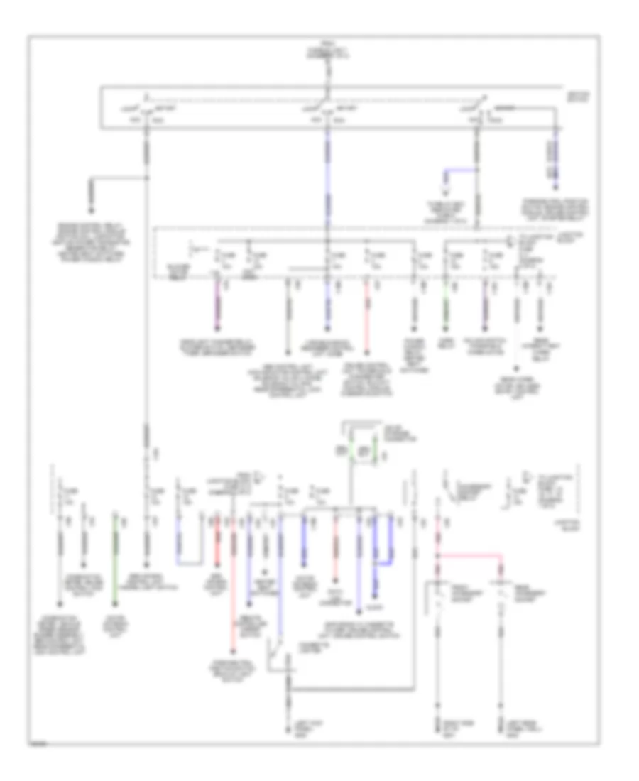
Power Distribution Wiring Diagram (1 of 2) for Mitsubishi Montero SR 1997

List of elements for Power Distribution Wiring Diagram (1 of 2) for Mitsubishi Montero SR 1997:
- (not used)
- Air conditioning compressor clutch
- Am/fm radio w/ cassette player, spare connector for cd audio changer, ignition keyhole illumination light timer
- Battery
- Blower motor relay
- C100
- C78
- C79
- C81
- C83
- C93
- C94
- C96
- C97
- Cargo space light, reading light, dome light, left vanity mirror light, right vanity mirror light
- Clock, multi meter, left front door light, right front door light, keyless entry control unit, elc-4a/t control module, buzzer assembly, cruise control unit, abs control unit
- Combination meter (beam)
- Condenser fan motor
- Data link connector
- Dedicated fuse (relay box)
- Dedicated fuses (relay box)
- Defogger relay
- Door lock control unit
- Door lock relay
- Door lock relay, combination meter
- Engine control module
- Engine control relay
- From c junction block fuse 14 (diagram 2 of 2)
- From ignition switch (diagram 2 of 2)
- Fuse 10a
- Fuse 15a
- Fuse 20a
- Fuse 25a
- Fusible link
- Fusible link 1 60a
- Fusible link 10 30a
- Fusible link 12 30a
- Fusible link 13 40a
- Fusible link 4 60a
- Fusible link 5 100a
- Fusible link 6 20a
- Fusible link 7 40a
- Fusible link 9 30a
- G102 (above left shock tower)
- G110 (left front of engine)
- Generator
- Hazard light switch
- Headlight relay
- Headlight washer motor
- Horn relay
- Hydraulic unit
- Iod or storage connector
- J/c 3 (left side of i/p)
- Junction block
- Left headlight, right headlight
- Left rear combination light, left front combination light, right front combination light, clock, headlight washer relay, right rear combination light, left license plate lamp, right license plate lamp, shock absorber control switch, rheostat, combination meter, power window main switch, left vanity mirror light, right vanity mirror light, ashtray illumination light, cigarette lighter illumination light, rear differential lock switch, heater control illumination light, power/hold changeover switch, hazard light switch, multi meter am/fm radio w/ cassette player, buzzer assembly, defogger switch, overdrive switch, cruise control main switch, diode
- Motor antenna control unit
- Nca
- Power window relay, power seat assembly
- Red
- Starter motor
- Stop light switch
- Sunroof switch
- Tail light relay
- To ignition switch (diagram 2 of 2)
Power Distribution Wiring Diagram (2 of 2) for Mitsubishi Montero SR 1997
List of elements for Power Distribution Wiring Diagram (2 of 2) for Mitsubishi Montero SR 1997:
- (a/t) (m/t)
- (left kick panel) g200
- (left rear wheel well) g402
- (not used)
- (right side of i/p) g201
- Abs control unit, 4wd indicator control unit, solenoid valve a, diode, solenoid valve b, rear differential lock control unit
- Acc
- Accessory socket relay
- Am/fm radio w/ cassette player, cruise control unit, cruise control switch
- Blower motor relay
- C100
- C101
- C80
- C81
- C93
- C94
- C95
- C96
- C97
- C98
- Cigarette lighter
- Clock
- Column switch, windshield wiper motor
- Combination meter, cruise control main switch
- Combination meter, vehicle speed sensor, buzzer assembly, abs control unit, rear differential lock control unit
- Cruise control unit, power/hold changeover switch, elc-4a/t control module, overdrive switch
- Data link connector
- Engine control relay, engine control module ignition coil, capacitor, ignition power transistor, generator relay, heated seat switches, power window relay
- From fusible link 7 (diagram 1 of 2)
- From junction block d
- Front accessory socket
- Fuse 10, 9 (diagram 2 of 2)
- Fuse 10a
- Fuse 15a
- Headlight washer relay, blower switch, defogger timer, defogger switch
- Heated seat switches
- Horn relay
- Ignition switch
- Iod or storage connector
- Junction block
- Lock
- Motor antenna control unit
- Park/neutral position switch, back-up light switch
- Park/neutral position switch, engine control module, cruise control unit, starter relay
- Pnk
- Power window relay, heated seat switches
- Rear accessory socket
- Rear intermittent
- Rear wiper motor, keyless entry control unit
- Red
- Relay
- Remote controlled mirror switch
- Run
- Srs air bag control unit, hazard light switch
- Srs air bag control unit
- Start
- To junction block fuse 1, 6, 16, 17, 19 (diagram 1 of 2)
- To junction block fuse 5, 4 (diagram 2 of 2)
- To relay box dedicated fuse 9 (diagram 1 of 2)
- Variable shock absorber control unit, diode
- Wiper