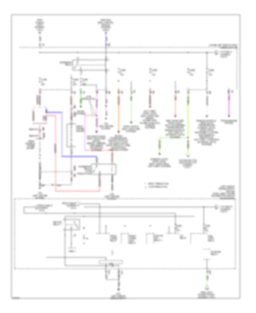
POWER DISTRIBUTION
Power Distribution Wiring Diagram (1 of 3) for Nissan Maxima SV 2012

List of elements for Power Distribution Wiring Diagram (1 of 3) for Nissan Maxima SV 2012:
- (at battery) fusible link box (battery)
- (left front of engine compt) fuse & fusible link box
- (left side of engine compt) ipdm e/r (intelligent power distribution module engine room)
- 82g
- Anti-lock brakes system
- Battery
- Circuit breaker (behind left side of dash)
- Cpu
- E16
- E18
- E201
- E30
- Ecm relay
- Engine controls system
- Exterior lights system
- Exterior lights, defogger, interior lights, headlights, seats, memory, wiper/washer, trunk, tailgate, fuel doors, power tops, anti-theft, body computer, door locks, warning & power windows systems
- F10
- Front fog lamp relay
- Fuse 10a
- Fuse 15a
- Fuse 30a
- Fusible link a 250a
- Fusible link b 80a
- Fusible link c 100a
- Fusible link d 60a
- Fusible link e 100a
- Fusible link f 50a
- Fusible link g 30a
- Fusible link h 40a
- Fusible link k 40a
- Fusible link l 40a
- Fusible link m 40a
- Headlamp high relay
- Headlamp low relay
- Headlights system
- Headlights, interior lights & exterior lights systems
- Horns, anti-theft & door locks systems
- Joint connector e01 (left side of engine compt)
- Navigation, air conditioning & sound systems
- Pnk
- Red
- Seats & memory systems
- Seats system
- Sound & navigation systems
- Starting/ charging system
- Tail lamp relay
- Throttle control motor relay
- To cpu (diagram 2 of 3)
- To front wiper relay (diagram 2 of 3)
- To fuse 5 (diagram 2 of 3)
- To starter relay (diagram 2 of 3)
- W/ bose audio system
- W/ heated steering wheel
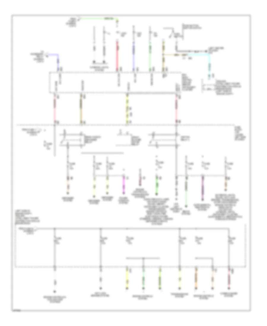
Power Distribution Wiring Diagram (2 of 3) for Nissan Maxima SV 2012
List of elements for Power Distribution Wiring Diagram (2 of 3) for Nissan Maxima SV 2012:
- (left side of engine compt) ipdm e/r (intelligent power distribution module engine room)
- (lower left side of dash) fuse block (j/b)
- 11p
- 12p
- A/c relay
- Accessory relay
- Accessory relay (late production)
- Air conditioning, body computer, sound, memory, mirrors, defogger & navigation systems
- Anti-theft, door locks, body computer, memory, power tops, power windows & warning systems
- Body computer, door locks, anti-lock brakes, transmissions, engine controls, anti-theft & exterior lights systems
- Cooling fan relay 1
- Cpu
- Door locks & body computer systems
- E15 (left side of engine compt)
- E17
- E18
- Early production
- From bcm (body control module) (diagram 3 of 3)
- From fuse 43 (diagram 1 of 3)
- From fuse 55 (diagram 1 of 3)
- From fusible link c (diagram 1 of 3)
- From joint connector e01 (diagram 1 of 3)
- Front console power socket
- Front power socket
- Front wiper high relay
- Front wiper relay
- Fuel pump relay
- Fuse 10a
- Fuse 15a
- Fuse 20a
- Ignition relay 1
- Interior lights, door locks, body computer & anti-theft systems
- Late production
- M205
- M79 (left center of dash)
- M87
- Red
- Sound systems
- Sound, transmissions, engine controls, air conditioning, computer data lines, navigation & mirrors systems
- Starter relay
- To fuse 10 (diagram 3 of 3)
- To fuse 33 (diagram 3 of 3)
- To push button ignition switch (diagram 3 of 3)
- Transmissions system
Power Distribution Wiring Diagram (3 of 3) for Nissan Maxima SV 2012
List of elements for Power Distribution Wiring Diagram (3 of 3) for Nissan Maxima SV 2012:
- (left center of dash) m79
- (left side of engine compt) ipdm e/r (intelligent power distribution module engine room)
- 10m
- 10t
- 11m
- 11t
- 12m
- 23g
- 29g
- Acc ind
- Acc led
- Anti-lock brakes system
- Bat bcm
- Bcm (body control module) (behind instrument cluster)
- Computer data lines, air conditioning, sound, memory, instrument cluster, transmissions, engine controls, body computer, electronic power steering, mirrors, warning, defogger & seats systems
- Cpu
- Defogger system
- E18
- E200
- E30
- Eng
- Engine controls & cooling fans systems
- Engine controls & transmissions systems
- Engine controls system
- F10
- Fan rly
- From fuse 11 d (diagram 2 of 3)
- From fuse 32 f (diagram 2 of 3)
- From g fuse 9 (diagram 2 of 3)
- Front blower motor relay
- Fuse 10a
- Fuse 15a
- Fuse 20a
- Fuse block (j/b) (lower left side of dash)
- Ign on led
- Ign rly out 2
- Ignition relay 2
- Ill
- Interior lights system
- Ipdm e/r (intelligent power distribution module engine room) (left side of engine compt)
- Lock ind
- M17
- M18
- M19
- M19 acc cont
- M21
- M79 (left center of dash)
- On ind
- Pnk
- Power windows system
- Push button ignition switch
- Push switch
- Rear def
- Rear window defogger relay
- Red
- S/l lck led
- Seats system
- To accessory relay (diagram 2 of 3)
- Transmissions system
- Wiper/washer system