POWER DISTRIBUTION
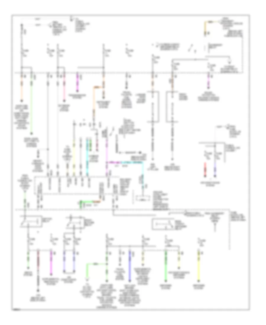
Power Distribution Wiring Diagram (1 of 2) for Nissan Quest S 2014

List of elements for Power Distribution Wiring Diagram (1 of 2) for Nissan Quest S 2014:
- (left side of engine compt) ipdm e/r (intelligent power distribution module engine room)
- (not used)
- A/c relay
- Ac 120v outlet
- Ac 120v outlet main switch
- Anti-lock brakes & navigation systems
- Anti-lock brakes system
- B204
- B224 m71
- B225
- B270
- B85
- Bat (f/l)
- Battery
- Battery terminal w/ fusible link
- Bcm (body control module) (behind left side of dash)
- Cooling fan relay 1
- Cooling fans system
- Cpu
- E10
- E103
- E105 m11
- E106
- E13
- E21 (rear of engine)
- E345
- E346
- Ecm relay
- Electronic power steering system
- Engine controls system
- Engine controls, anti-theft & door locks systems
- Exterior lights system
- F12
- From battery terminal w/ fusible link (diagram 1 of 2)
- From fuse block j/b (diagram 2 of 2)
- Front fog lamp relay
- Front wiper high relay
- Front wiper relay
- Fuel pump relay
- Fuse & fusible link block (left side of engine compt)
- Fuse & fusible link holder 2
- Fuse 10a
- Fuse 15a
- Fuse 20a
- Fuse 30a
- Fuse block (j/b) (behind b6
- Fuse n/a
- Fusible link a 250a
- Fusible link b 100a
- Fusible link c 60a
- Fusible link d 100a
- Fusible link e 80a
- Fusible link f 30a
- Fusible link g 20a
- Fusible link h 40a
- Fusible link j 40a
- Fusible link k 40a
- Fusible link l 40a
- Fusible link m 40a
- Fusible link n 100a
- Headlamp high relay
- Headlamp low relay
- Headlights system
- Horns system
- Ignition relay
- Interior lights & exterior lights systems
- Interior lights system
- Inverter unit
- Left side of dash)
- M123
- M43 (behind right side dash)
- M76 (behind left side of dash)
- M79
- Memory, seats & door locks systems
- Navigation & sound systems
- Nca
- Option connector (trailer)
- Pnk
- Red
- Seats system
- Starter relay
- Starting/ charging system
- Tail lamp relay
- Throttle control motor relay
- To fuse block j/b (diagram 2 of 2)
- To ipdm e/r (intelligent power distribution module engine room) (diagram 1 of 2)
- Transmissions system
- Trunk, tailgate, fuel doors & door locks systems
- Wiper/ washer system
- Wiper/washer system
Power Distribution Wiring Diagram (2 of 2) for Nissan Quest S 2014
List of elements for Power Distribution Wiring Diagram (2 of 2) for Nissan Quest S 2014:
- (behind left side of dash) fuse block (j/b)
- (f/b) cont ign rly
- 10c
- 10g
- 11c
- 11f
- 12c
- 12f
- 12g
- Acc
- Acc ind
- Accessory relay
- Air conditioning & defogger systems
- Air conditioning system
- Anti-lock brakes, shift interlock, electronic power steering, exterior lights, engine controls & air conditioning systems
- B26 (left "c" pillar)
- Bat (fuse)
- Bcm (body control module) (behind left side of dash)
- Computer data lines, air conditioning, anti-lock brakes, trunk, tailgate, fuel doors, navigation, sound & mirrors systems
- Computer data lines, air conditioning, door locks, anti-theft, mirrors navigation & sound systems
- Cont acc rly
- Cont out blwr rly
- Cpu
- Def rly rr wind
- Defogger system
- Door locks, anti-theft & warning systems
- E10
- E101
- E102
- E103
- E105
- E105 m11
- Exterior lights system
- From accessory relay (diagram 2 of 2)
- From battery terminal w/ fusible link (diagram 1 of 2)
- From bcm(body control module) (diagram 2 of 2)
- From fuse & fusible link block (diagram 1 of 2)
- From fuse 8 d (diagram 2 of 2)
- From fuse block j/b (diagram 2 of 2)
- Front blower relay
- Front power socket
- Fuse & fusible link holder 1
- Fuse 10a
- Fuse 15a
- Fuse 20a
- Fuse block (j/b) (behind left side of dash)
- Ignition relay
- Illumi- nation
- Instrument cluster system
- Interior lights system
- Ipdm e/r (intelligent power distribution module engine room) (left side of engine compt)
- Lock
- Lock ind
- Luggage room power socket
- M11
- M121
- M123
- M124
- M35 (behind right side of dash)
- M43 (behind right side of dash)
- M76 (behind left side of dash)
- Memory, warning & door locks systems
- On ind
- Pnk
- Push button ignition switch (left center of dash)
- Push sw
- Push switch
- Rear window defogger relay
- Red
- Seats system
- Sound, navigation, air conditioning & mirrors systems
- Stop lp sw2
- To ac 120v outlet main switch (diagram 1 of 2)
- To front blower relay (diagram 2 of 2)
- To fuse & fusible link holder 1 (diagram 2 of 2)
- To fuse block j/b (diagram 2 of 2)
- To rear window defogger relay (diagram 2 of 2)
- Transmissions system
- Trunk, tailgate, fuel doors system
- Trunk, tailgate, fuel doors, seats & warning systems