POWER DISTRIBUTION
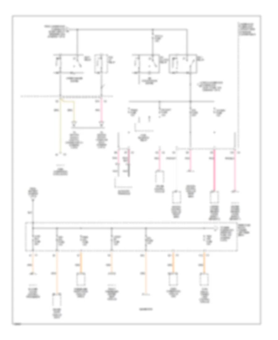
Power Distribution Wiring Diagram (1 of 5) for Oldsmobile Aurora 2003

List of elements for Power Distribution Wiring Diagram (1 of 5) for Oldsmobile Aurora 2003:
- (at right side of engine compartment) underhood fuse block
- (w/ 1 air pump)
- Abs fuse 50a
- Air pump a fuse 50a
- Air pump b fuse 50a
- Air pump fuse 50a
- Battery
- Coil
- Contact
- Cool fan 1 fuse 30a
- Cool fan 2 fuse 30a
- Cool fan s/p relay
- Drl relay
- Electronic brake control module (ebcm)
- Evaporative emissions (evap) canister purge solenoid
- Fog drl fuse 15a
- Fog lp relay
- Fuel injector
- Generator
- Hdlp hi bm relay
- Hdlp lo bm relay
- High speed cool fan 2 relay
- Horn fuse 15a
- Horn relay
- Ign 1 fuse 10a
- Injr 1 fuse 10a
- Injr 2 fuse 10a
- Low speed cool fan 1 relay
- Mass air flow sensor
- Pcm batt fuse 10a
- Pcm ign fuse 10a
- Pnk
- Powertrain control module (pcm)
- Red
- Refer to starting/charging system
- Secondary air injection (air) bypass valve solenoid (calif)
- Secondary air injection (air) pump relay a
- Secondary air injection (air) pump relay a (calif)
- Secondary air injection (air) pump relay b
- Secondary air injection (air) pump relay b (calif)
- Secondary air injection pump relay
- Start 1 relay
- Start circuit breaker 30a
- Starter solenoid
- Tcc/ cruise release switch
- Theft deterrent control module
- To rear fuse block (diagram 2 of 5)
- To underhood fuse block (accy relay) (diagram 2 of 5)
- To underhood fuse block (ign 1 relay) (diagram 2 of 5)
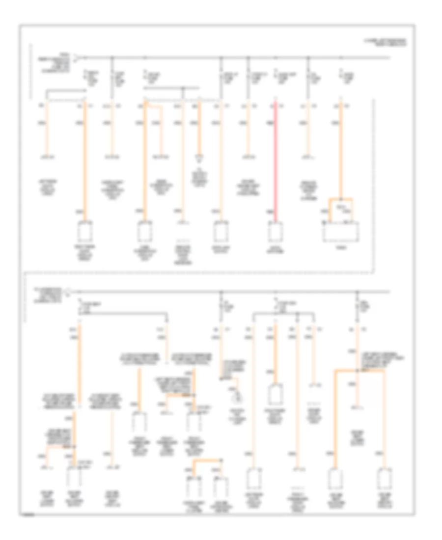
Power Distribution Wiring Diagram (2 of 5) for Oldsmobile Aurora 2003
List of elements for Power Distribution Wiring Diagram (2 of 5) for Oldsmobile Aurora 2003:
- A/c clu fuse 15a
- A/c clutch relay
- A12
- Accy relay
- Air conditioning system
- Automatic transaxle
- B12
- Blower motor control processor
- Cr cont fuse 10a
- Cruise control module
- Dash integration module (dim)
- Dim fuse 10a
- Dis fuse 20a
- Driver door module (ddm)
- Drv mdl fuse 10a
- E10
- E11
- F12
- Fog lp relay
- From battery (diagram 1 of 5)
- From underhood fuse block (injr 1 fuse, 10a) (diagram 1 of 5)
- From underhood fuse block (start circuit breaker, 30a) (diagram 1 of 5)
- Front passenger heated seat module
- Generator
- Heated oxygen sensor (ho2s) (bank 1, sensor 2)
- Heated oxygen sensor (ho2s) (bank 2, sensor 1)
- Htdst rf fuse 10a
- Hvac blo fuse 30a
- Hvac solenoid relay
- Ign 1 relay
- Ignition control module front bank
- Ignition control module rear bank
- Nca
- Oxy sen fuse 10a
- Pass mdl fuse 10a
- Passenger front door module (pfdm)
- Pnk
- Rear fuse block (under left rear seat)
- To ignition switch (cavity c, connector c1) (diagram 4 of 5)
- To ignition switch (via splice s210) (diagram 4 of 5)
- To rear fuse block (rrdr mdl fuse, 10a) (diagram 3 of 5)
- Trans fuse 10a
- Tsig/ haz fuse 15a
- Turn signal/ hazard lamp control module
- Underhood fuse block (at right side of engine compartment)
- Wiper/washer system
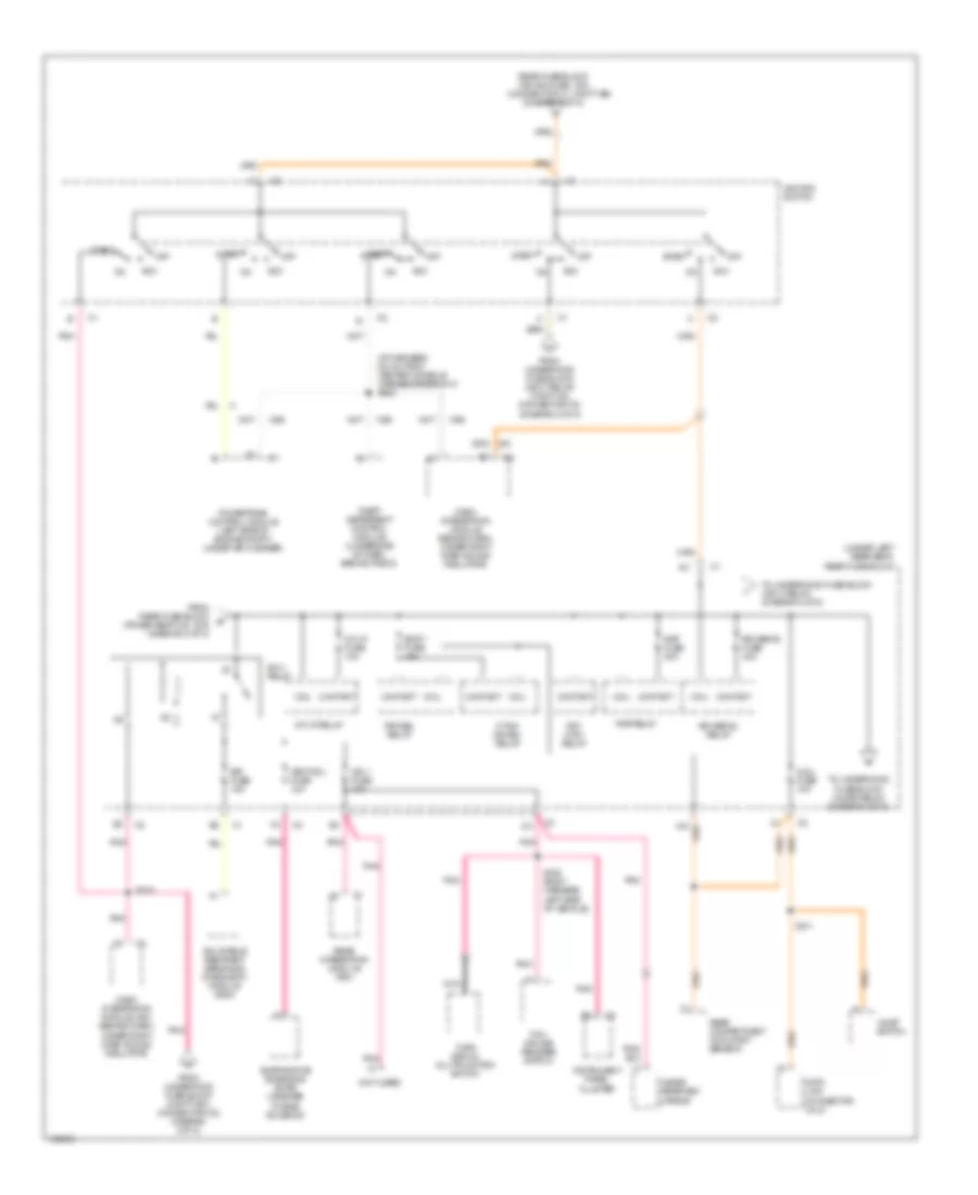
Power Distribution Wiring Diagram (3 of 5) for Oldsmobile Aurora 2003
List of elements for Power Distribution Wiring Diagram (3 of 5) for Oldsmobile Aurora 2003:
- (driver seat harness, 6 cm from power seat switch) s325
- (i/p harness, 13 cm from c216 break- out) s206
- (left seat harness, under left front seat, 21 cm from seat harness clip) s317
- (left seat harness, under left front seat, 9.5 cm from right seat clip) s323
- (under left rear seat) rear fuse block
- (w/ a81)
- (w/o a81)
- A11
- Audio amp fuse 20a
- Audio amplifier
- Audio fuse 10a
- Cd fuse 10a
- D12
- Dash integration module (dim)
- Driver door module (ddm)
- Driver heated seat module (if equipped)
- Driver information center
- Driver memory seat module
- Driver seat adjuster switch
- Driver seat lumbar switch
- Driver seat memory module
- E10
- E12
- F12
- From rear fuse block (tsig/haz fuse, 15a) (diagram 2 of 5)
- Front passenger door module (pfdm)
- Front passenger seat adjuster switch
- Front passenger seat lumbar switch
- Front passenger seat recline switch
- H a
- Htdst lf fuse 10a
- Hvac bat fuse 10a
- I/p fuse 10a
- Ign sw fuse 15a
- Ignition key cylinder lamp
- Instrument panel cluster
- Instrument panel integration module (ipm)
- Left rear door module (lrdm)
- Mem fuse 10a
- Pwr seat c.b. 30a
- Pwr wdo c.b. 30a
- Radio
- Rear integration module (rim)
- Red
- Remote control door lock receiver
- Remote playback device cd changer
- Right rear door module (rrdm)
- Rrdr mdl fuse 10a
- S210
- Stop lp fuse 15a
- Stoplamp switch
- To ignition switch (diagram 4 of 5)
- To underhood fuse block (ign 1 relay) (diagram 4 of 5)
- W/ front passenger power seat adjuster, multi-directional
- W/ memory seat adjuster, mirror, power driver personalization
- W/o front passenger power seat adjuster, multi-directional
- W/o memory seat adjuster, mirror, power driver personalization
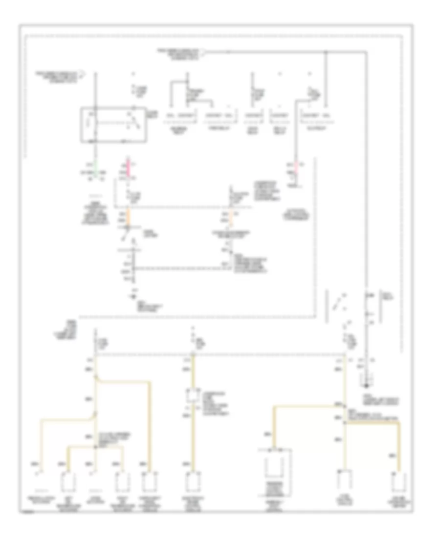
Power Distribution Wiring Diagram (4 of 5) for Oldsmobile Aurora 2003
List of elements for Power Distribution Wiring Diagram (4 of 5) for Oldsmobile Aurora 2003:
- (connector c1, cavity e9)
- (diagram 3 of 5)
- (i/p harness, 6.5 cm from center console harness breakout) s208
- (not used)
- (under left rear seat) rear fuse block
- A11
- Acc
- Aldl fuse 10a
- Body fuse 15a
- Coil
- Contact
- Dash integration module (behind dash, under right dash sound insulator)
- Dash integration module (dim) (behind dash, under right dash sound insulator)
- Data link connector (dlc)
- Evaporative emissions (evap) canister purge solenoid
- F/tnk dr rel relay
- From rear fuse block (power seat c.b., 30a) (diagram 3 of 5)
- From underhood fuse block (accy relay) (cavity d2, connector c2) (diagram 2 of 5)
- From underhood fuse block (cavity e10, connector c2) (diagram 2 0f 5)
- Frt ctsy relay
- Ign 1 fuse 10a
- Ign 1 relay
- Ignition switch
- Inflatable restraint sensing & diagnostic module (sdm)
- Inside rearview mirror
- Instrument panel cluster
- Int lp fuse 10a
- Int lp relay
- Nca
- Off
- Pnk
- Powertrain control module (left side of engine compt, under air cleaner)
- Rap fuse 20a
- Rap relay
- Rear compartment occupant sensor
- Rear fuse block (ign sw fuse, 15a)
- Rear integration module (rim)
- Rr defog fuse 40a
- Rr defog relay
- S210
- S211
- S216 (body harness, left side of vehicle)
- Sir fuse 15a
- Start
- Tcc/ cruise release switch
- Theft deterrent control module (underside of dash, behind radio)
- To underhood fuse block (cigar relay) (diagram 5 of 5)
- To underhood fuse block (ign 3 relay) (diagram 5 of 5)
- Trk rel relay
- Turn signal/ multifunction switch
- Valet switch
- Vent sol fuse 10a
Power Distribution Wiring Diagram (5 of 5) for Oldsmobile Aurora 2003
List of elements for Power Distribution Wiring Diagram (5 of 5) for Oldsmobile Aurora 2003:
- (diagram 4 of 5)
- (in hvac harness, 30 cm from c204 breakout) s221
- A10
- A11
- Abs fuse 10a
- Assembly shift control
- Automatic level control compressor
- Aux pwr fuse 20a
- B10
- B12
- C/ltr fuse 20a
- C11
- C12
- Cigar fuse 40a
- Cigar lighter
- Cigar relay
- Coil
- Console accessory power outlet
- Contact
- D10
- D12
- Driver information center
- E12
- Elc fuse 30a
- Elc relay
- Electronic brake control module
- F/pmp fuse 20a
- F/pmp relay
- From rear fuse block (prk/brk fuse, 20a) (diagram 4 of 5)
- From rear fuse block (rr defog relay) i
- G201 (behind right kick panel)
- G302 (under left side of rear seat cushion)
- Hvac control module
- Hvac fuse 10a
- Ign 3 relay
- Ign 3 rr fuse 10a
- Instrument panel integration module
- Left air temperature actuator
- Mode actuator
- Nca
- Park relay
- Pnk
- Prk lp relay
- Prk/rev fuse 10a
- Rear fuse block (under left rear seat)
- Rear integration module (near upper left corner of rear shelf)
- Recirculation actuator
- Red
- Reverse lockout control actuator
- Reverse relay
- Right air temperature actuator
- S200 (i/p harness, 15 cm from data link connector)
- S209
- S228 (center console harness, near auxiliary power outlet breakout)
- Underhood fuse block (at right side of engine compartment)