POWER DISTRIBUTION
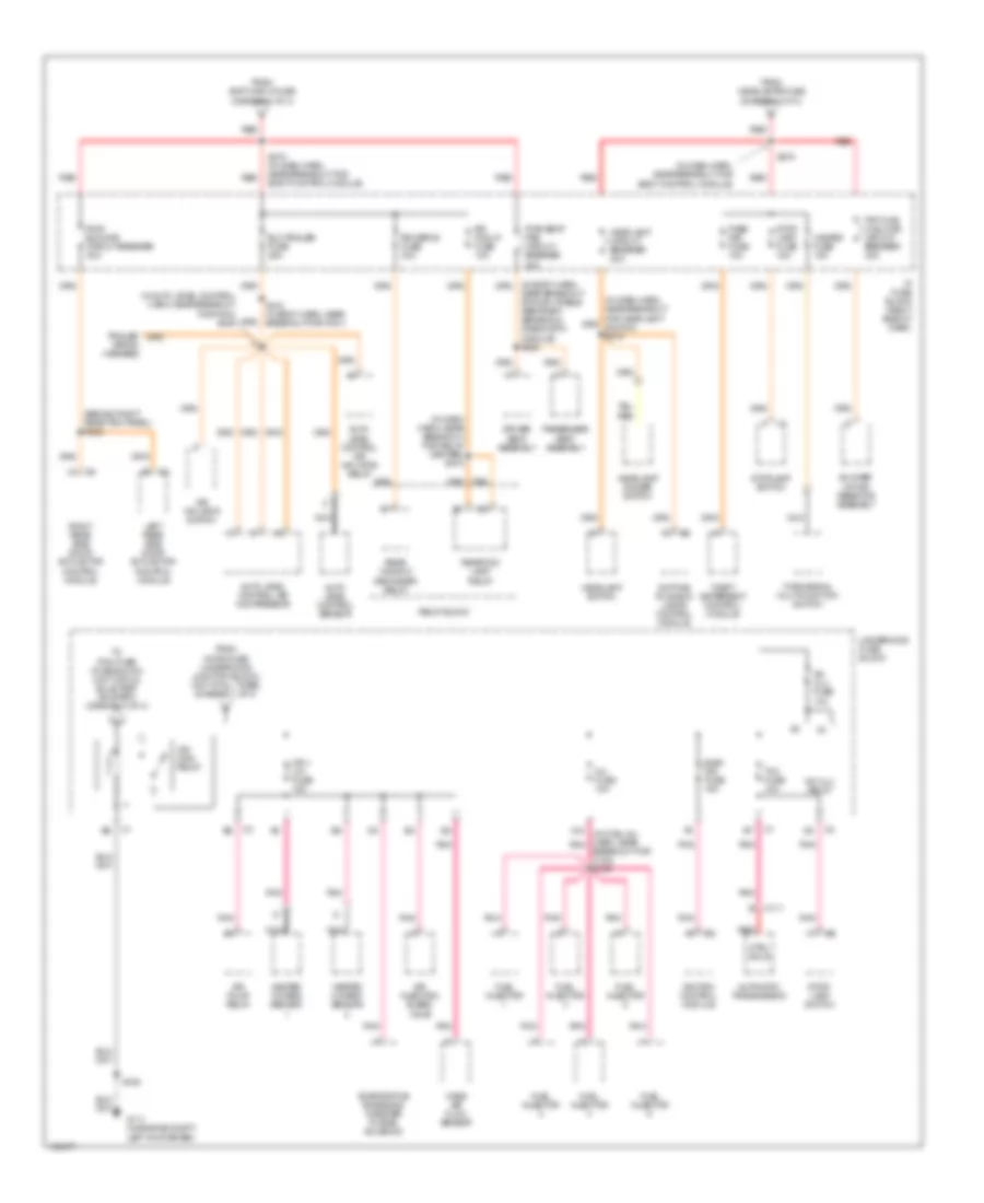
Power Distribution Wiring Diagram (1 of 4) for Oldsmobile Silhouette GLS 2003

List of elements for Power Distribution Wiring Diagram (1 of 4) for Oldsmobile Silhouette GLS 2003:
- (diagram 1 of 4)
- (diagram 2 of 4)
- (diagram 3 of 4)
- (in body harn, at letf rear wheelwell) s326
- (in dash harn, near break- out for wiper/washer & multifubction switch)
- (in dash harn, near breakout for cigar lighter)
- Air pump fuse 30a
- Air pump relay
- Alt/ sense fuse 10a
- B/u lamp fuse 10a
- Batt main 1 fuse 60a
- Batt main 2 fuse 60a
- Battery
- Body control module
- Cigar lighter
- Cigar/dlc/ apo frt fuse 15a
- Cluster batt fuse 10a
- Cool fan 1 fuse 30a
- Cool fan 1 relay
- Cool fan 2 fuse 30a
- Cool fan 2 relay
- Cool fan relay
- Ctsy lamp fuse 10a
- Data link connector
- Daytime running lamps control module
- Driver information center (dic)
- E12
- E16
- Ecm sense fuse 10a
- Electronic brake control module
- Fog lamp relay
- Fog lp fuse 10a
- From radio fuse a
- Front auxiliary power outlet
- Fuel pump fuse 15a
- Fuel pump relay
- Fusible link a (10ga- rust)
- G200 (at right side of dash)
- Generator
- Head- lamps fuse 60a
- Headlamp switch
- Horn fuse 15a
- Horn relay
- Hvac control module
- Ign main 1 fuse 40a
- Ign main 2 fuse 60a
- Ign main relay (diagram 2 of 4)
- Instrument panel cluster (ipc)
- Ip fuse block (right side of dash)
- Left sliding door module
- Onstar fuse 10a
- Outside rearview mirror switch
- Park lp fuse 20a
- Park/ neutral position switch
- Powertrain control module
- Pwr lock fuse 20a
- Pwr mirror fuse 10a
- Radio
- Radio fuse 10a
- Rap relay fuse 10a
- Rear auxiliary power outlet
- Red
- Remote control door lock receiver
- Right sliding door module
- Rr pwr sckt fuse 20a
- S202
- S212
- S213
- S238
- S276 (in dash harn, near break- out for body control module)
- Starter
- Starter relay
- Theft led
- To cool fan 1 fuse (diagram 1 of 4)
- To ignition switch pin d2
- To ignition switch pin d5
- To rap relay (diagram 4 of 4)
- To s274
- To s278
- Underhood fuse block
- Vehicle interface unit (viu)
Power Distribution Wiring Diagram (2 of 4) for Oldsmobile Silhouette GLS 2003
List of elements for Power Distribution Wiring Diagram (2 of 4) for Oldsmobile Silhouette GLS 2003:
- (behind right rear trim panel) s322
- (diagram 1 of 4)
- (in auto level control harn, near breakout for p403) s445
- (in dash harn, near breakout for body control module)
- (in dash harn, near breakout for relay center) s270
- (in fuel inj harn, near pnk
- A/c clu fuse 10a
- A/c clu relay
- A12
- Air inflator switch
- Air injection bleed valve
- Air pump relay
- Auto level control air compressor
- Auto level control air inflator relay
- Auto level control sensor
- Automatic transmission
- Blower motor resistor assembly
- Breakout for c102) s109
- C111
- Ctrl sols
- Daytime running lamps control module
- Driver seat assembly
- Elc/trailer fuse 25a
- Elek ign fuse 15a
- Evaporative emissions canister purge solenoid
- From batt main 2 fuse
- From headlamps fuse
- From horn fuse (underhood junction block) (hot at all times) (diagram 1 of 4)
- Frt hvac hi blowr circuit breaker 30a
- Fuel injector
- G111 (in engine compt, left of starter)
- Hazard fuse 15a
- Headlamp circuit breaker 20a
- Headlamp dimmer switch
- Headlamp switch
- Heated oxygen sensor
- Ign i- u/h fuse 15a
- Ign main relay
- Ignition control module
- Inj fuse 10a
- Ip fuse block (right side of dash)
- Left rear side door actuactor control module
- Mass air flow sensor
- Nca
- Near breakout for inflatable restraint sensing & diagnostic module) s302
- Pass key fuse 10a
- Passenger seat assembly
- Pnk
- Pwr seat/ psd circuit breaker 30a
- Pwr sldg dr circuit breaker 30a
- Rear fog lamp relay
- Rear window defogger relay
- Red
- Relay block
- Right rear side door actuactor control module
- Rr defog fuse 30a
- Rr fog lp fuse 10a
- S106
- S274 (in dash harn, near breakout for body control module)
- S278
- S412 (in body harn, near breakout for p401)
- Stop lamp fuse 15a
- Stop- lamp switch
- Stoplamp switch
- Tcc fuse 10a
- Theft deterrent control module
- To pcm fuse (fuse block) (hot in run, bulb test or start) (diagram 3 of 4)
- Trailer wiring harness
- Turn/signal multifunction switch
- Underhood fuse block
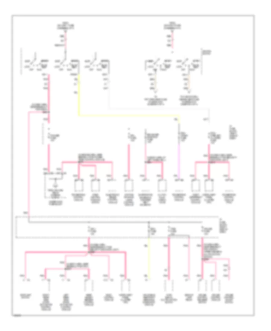
Power Distribution Wiring Diagram (3 of 4) for Oldsmobile Silhouette GLS 2003
List of elements for Power Distribution Wiring Diagram (3 of 4) for Oldsmobile Silhouette GLS 2003:
- (in body harn, at left wheelwell) s391
- (in body harn, near breakout for p401) s337
- (in dash harn, near breakout for radio) s228
- (in dash harn, near breakout for window wiper/washer & multifunction switch) s266
- (in dash harn, near pnk
- (in dash harn, pnk near breakout for security indicator light) s209
- (in engine harn, near breakout for power- train control module) s108
- A11
- A13
- Acc
- Acc 1
- Backup lamp relay
- Body control module
- Breakout for security indicator light) s210
- Bulb test
- C10
- C13
- Clutch pump check valve
- Crank
- Cruise control module
- Cruise control on/off switch
- Cruise control release switch
- Cruise fuse 10a
- D11
- Daytime running lamps control module
- Drl fuse 10a
- Electronic brake control module
- Enhanced evap/awd fuse 15a
- Evaporative emissions canister vent solenoid
- From ign main 1 fuse (diagram 1 of 4)
- From ign main 2 fuse (diagram 1 of 4)
- From ign main relay (diagram 2 of 4)
- Ign 0
- Ign 1
- Ign 1 fuse 10a
- Ign 3
- Ignition switch
- Inflatable restraint sensing & diagnostic module
- Instrument panel cluster (ipc)
- Ip fuse block (right side of dash)
- Left rear side door actuactor control module
- Lock
- Off
- Park/ neutral position switch
- Pcm/ crank fuse 10a
- Pcm/ pass key/ cluster fuse 10a
- Pcm/abs fuse 10a
- Pnk
- Powertrain control module
- Powertrain control module (pcm)
- Rear object sensor control module
- Red
- Right rear side door actuactor control module
- Run
- Sdm fuse 15a
- Start
- Stoplamp switch
- T/sig fuse 10a
- Theft deterrent control module
- To frt wpr/wshr fuse (fuse block) (diagram 4 of 4)
- To hvac/dic/drl/ heated seat fuse (fuse block) (diagram 4 of 4)
- Turn signal/ multifunction switch
- Underhood fuse block
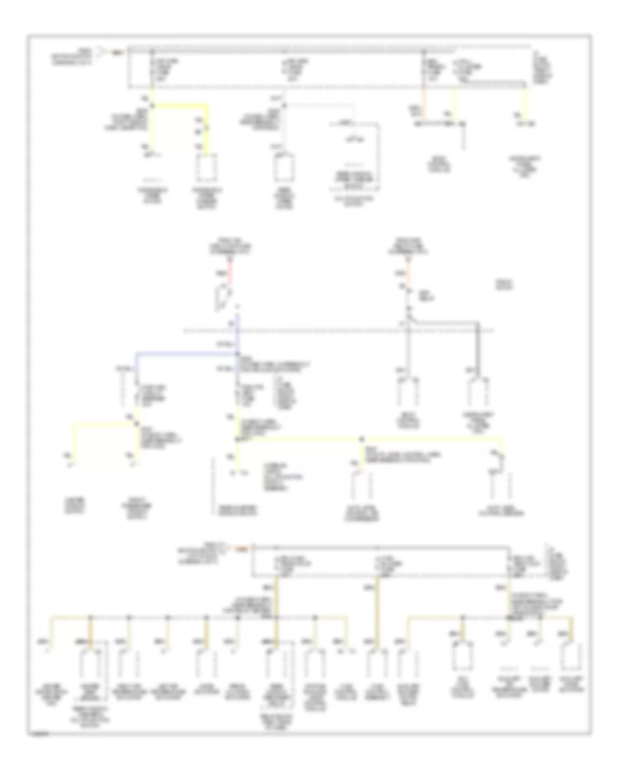
Power Distribution Wiring Diagram (4 of 4) for Oldsmobile Silhouette GLS 2003
List of elements for Power Distribution Wiring Diagram (4 of 4) for Oldsmobile Silhouette GLS 2003:
- (diagram 3 of 4)
- (in body harn, near breakout for c302) s317
- (in body harn, near breakout for left sliding door jamb switch) s345
- (in dash harn, near breakout for relay center) s264
- Auto level control air compressor
- Auto level control sensor
- Aux hvac control module
- Auxiliary air temperature actuator
- Auxiliary blower motor
- Auxiliary blower motor relay
- Auxiliary mode actuator
- Bcm prgrm fuse 10a
- Body control module
- Daytime running lamps control module
- Driver information center (dic)
- Drl/hvac/ temp/htd st fuse 10a
- From ign main 2 maxi fuse (diagram 1 of 4)
- From ignition switch
- From ignition switch j (hot in run) (diagram 3 of 4)
- From rap relay fuse (diagram 1 of 4)
- Front passenger window switch
- Frt wpr/ wshr fuse 25a
- Heated seat switch
- Hvac blower fuse 25a
- Hvac control assembly
- Hvac control module
- Instrument panel cluster (ipc)
- Interior lamp & multifunction switch assembly
- Ip fuse block (right side of dash)
- Left air temperature actuator
- Mall/ cluster fuse 10a
- Master window switch
- Mode actuator
- Multifunction switch
- Nca
- Pwr otr vent fuse 10a
- Pwr wdo circuit breaker 30a
- Rap relay
- Rear quarter window switch
- Rear window defogger relay
- Rear window washer & multifunction switch
- Rear window wiper motor
- Rear window wiper/ washer switch
- Recir- culation actuator
- Red
- Relay block
- Relay block (right side of dash)
- Right air temperature actuator
- Rr hvac/ temp cont fuse 25a
- Rr wpr/ wshr fuse 20a
- S245 (in dash harn, near breakout for radio)
- S249 (in dash harn, right side of dash, near p100)
- S263 (in dash harn, in breakout for air inlet actuator)
- S307 (in body harn, near breakout for c302)
- S440 (in auto level control harn, near breakout for p403)
- Windshield wiper motor
- Windshield wiper/ washer switch