POWER DISTRIBUTION
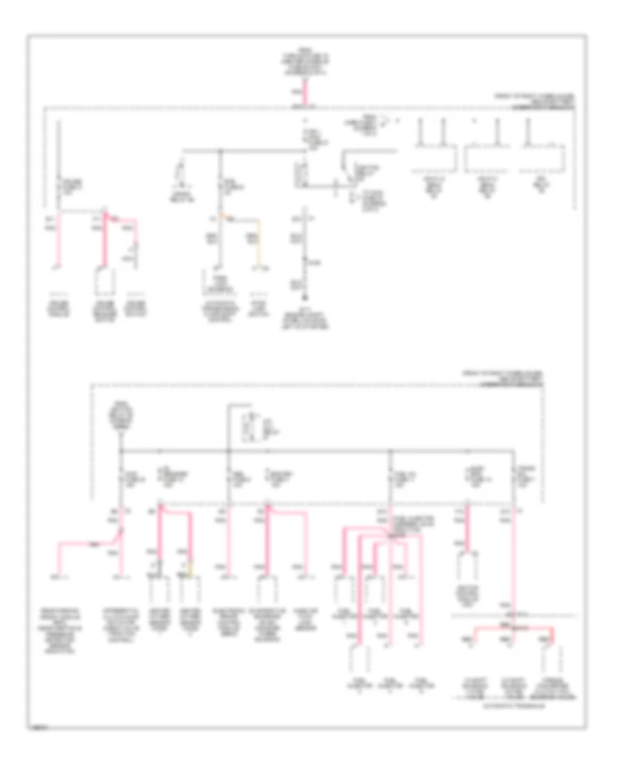
Power Distribution Wiring Diagram (1 of 4) for Pontiac Aztek Rally 2005

List of elements for Power Distribution Wiring Diagram (1 of 4) for Pontiac Aztek Rally 2005:
- (body harness, under left rear of vehicle, 7cm from c302 breakout) s305
- (diagram 1 of 4)
- (front of right wheelhouse, above battery) underhood fuse block
- (in floor console) center console fuse block
- (not used)
- (right side of dash, on underside of cross-car beam) g200
- A/c clu fuse 2 10a
- A/c clu relay
- A12
- Abs mtr fuse 35 40a
- Abs sol fuse 9 25a
- Acc pwr fuse 28 10a
- Accy diode (diagram 3 of 4)
- Accy relay
- Audio amplifier (w/ performance enhance audio)
- Automatic a/c
- Automatic level control (alc) sensor (if equipped)
- Auxiliary drop connector
- B12
- Batt 1 fuse 47 60a
- Batt 2 fuse 44 60a
- Batt 3 fuse 41 60a
- Battery
- Bcm fuse 28 10a
- Bcml fuse 36 20a
- Blower motor control processor
- Blower motor resistor assembly
- Body control module
- Body control module (bcm)
- C1 f10
- C11
- C2 a10
- Center console auxiliary power outlet
- Cigar lighter
- Cool fan 1 fuse 39 30a
- Cool fan 1 relay
- Cool fan 2 fuse 38 30a
- Cool fan 2 relay
- Cool fan s/p relay
- Crank relay
- D11
- D12
- Data link connector (dlc)
- Digital radio receiver
- Dvd fuse 25 15a
- E11
- E12
- Elc accy fuse 15 10a
- Electronic brake control module (ebcm)
- Evaporative emission (evap) canister vent solenoid
- F11
- F12
- Flasher (turn signal/ hazard flasher module) 10
- Fog lps fuse 26 10a
- Fog lps relay
- From ign 3 fuse 19 a
- From k
- Front passenger window switch
- Frt aux fuse 32 20a
- Fuel pump fuse 1 15a
- Fuel pump relay
- G200 (right side of dash, on underside of cross- car beam)
- Generator
- Hdlp lo beam relay 54 (diagram 2 of 4)
- Head up display (hud) (if equipped)
- Horn fuse 3 15a
- Horn relay
- Hud fuse 39 10a
- Hzd fl fuse 15a
- Ign 1 fuse 40 60a
- Ign 1/ ign 3 fuse 19 20a
- Ign 3 fuse 46 40a
- Inkey fuse 42 10a
- Manual a/c
- Park lps fuse 20 15a
- Park lps relay
- Pcm fuse 5 10a
- Powertrain control module (pcm)
- Pwr wdws circuit breaker 35 30a
- Radio
- Radio fuse 37 15a
- Rap relay
- Rd amp fuse 38 25a
- Rear seat enter- tainment (rse) assembly
- Red
- Red red
- Rr wpr fuse 32 20a
- S- band fuse 29 2a
- S213
- Splice pack sp250 (center dash next to light sensor)
- Starter
- Stoplamp switch
- Strtr sol fuse 34 40a
- Sun rf fuse 34 20a
- Sunroof module (if equipped)
- Theft deterrent control module
- To batt 1 fuse 47 (diagram 1 of 4)
- To ign 3 relay (diagram 3 of 4)
- To ignition switch pin b (diagram 3 of 4
- To ignition switch pin f (diagram 3 of 4)
- To ip mdl fuse 41 (diagram 4 of 4)
- To rear defog relay 20 (diagram 3 of 4)
- To rr aux fuse 14 (diagram 4 of 4)
- Turn signal/ multi- function switch
- Vehicle communication interface module (vcim)
- Vent sol fuse 24 10a
- Window master switch
- Windshield wiper motor
- Wiper fuse 29 25a
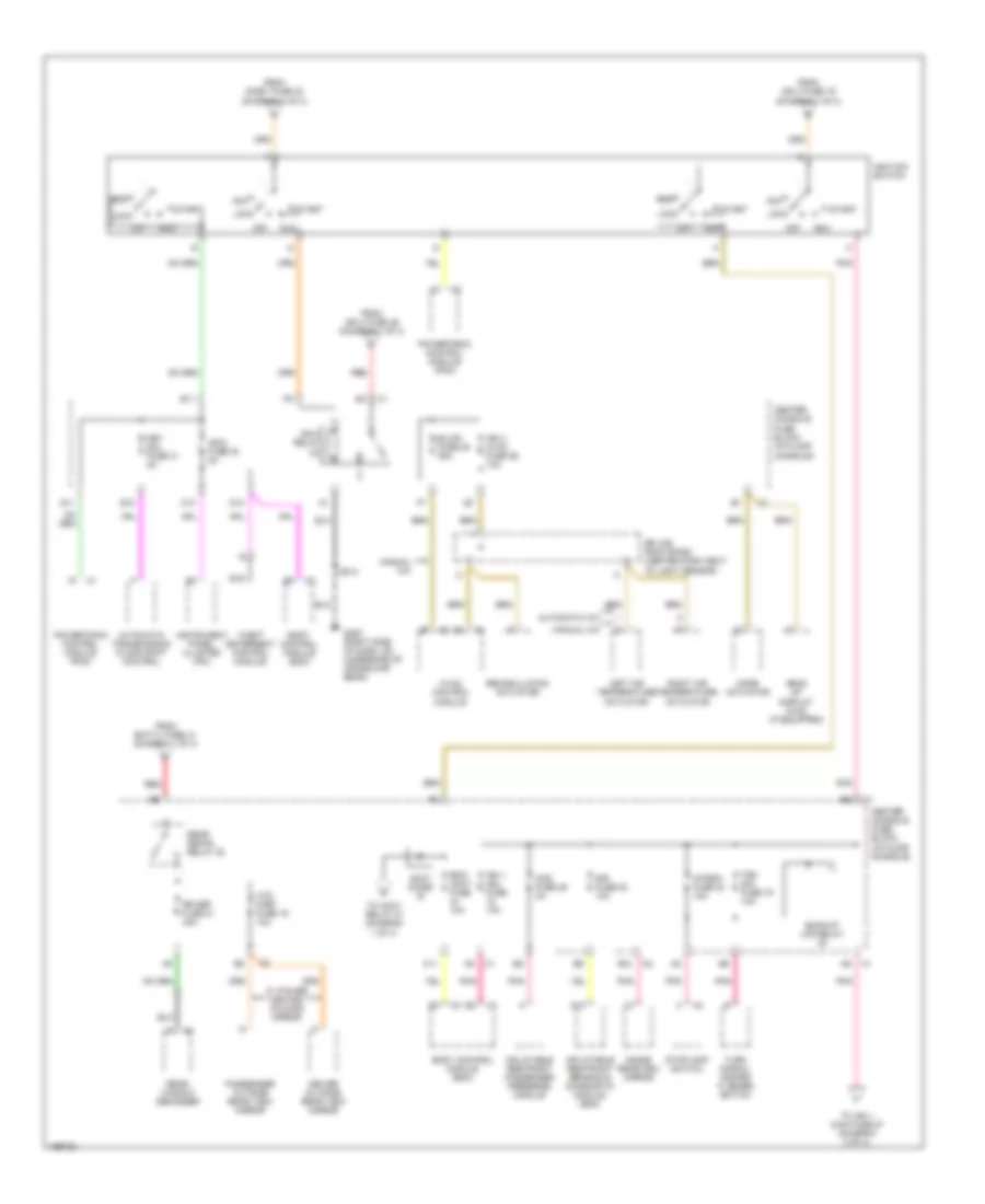
Power Distribution Wiring Diagram (2 of 4) for Pontiac Aztek Rally 2005
List of elements for Power Distribution Wiring Diagram (2 of 4) for Pontiac Aztek Rally 2005:
- (front of right wheelhouse, above battery) underhood fuse block
- (fuel injector pnk
- 1-2 shift solenoid (1-2 ss) valve
- 2-3 shift solenoid (2-3 ss) valve
- A/c clu relay
- Abs fuse 6 10a
- Automatic transaxle
- Automatic transmission floor shift control
- Awd fuse 30 15a
- B10
- Btsi fuse 33 2a
- Crank relay 59
- Cruise control module
- Cruise control release switch
- Cruise control switch
- Cruise fuse 31 10a
- D12
- Differential clutch pump actuator check valve (traction control)
- Drl relay
- E c111
- E11
- E12
- Elec eng fuse 13 15a
- Electronic brake control module (ebcm)
- Ems dev fuse 4 10a
- Evaporative emissions (evap) canister purge solenoid
- F11
- F12
- From horn fuse 3 c (diagram 1 of 4)
- From ignition relay 59 diagram (2 of 4)
- From turn sig fuse 19 (center console fuse block) (diagram 3 of 4)
- Fuel inj fuse 11 15a
- Fuel injector
- G111 (engine compt, on bellhousing, left of starter)
- Harness, 39 cm from c102) s109
- Hdlp hi beam relay
- Hdlp lo beam relay
- Heated oxygen sensor (ho2s)
- Ign 1 main fuse 27 10a
- Ignition control module (icm)
- Ignition relay
- Mass air flow (maf) sensor
- Nca
- O2 sensors fuse 10 15a
- Park lock solenoid
- Pnk
- Rear parking assist module (rpa) (near obstacle presence detection sensor indication)
- Red
- S106
- S115
- Stop- lamp switch
- To awd fuse 30 (diagram 2 of 4)
- Torque converter clutch (tcc) solenoid valve
- Trans sol fuse 7 10a
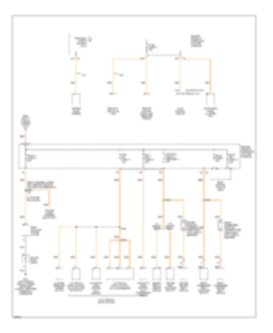
Power Distribution Wiring Diagram (3 of 4) for Pontiac Aztek Rally 2005
List of elements for Power Distribution Wiring Diagram (3 of 4) for Pontiac Aztek Rally 2005:
- A10
- Acc
- Accy diode
- Aos fuse 46 2a
- Automatic a/c
- Automatic transmission floor shift control
- B12
- Backup lps relay
- Bcm- accy fuse 10a
- Blwr fuse 25 25a
- Body control module (bcm)
- C10
- C11
- Center console fuse block (in floor console)
- D10
- D11
- Driver outside rear view mirror
- E10
- E11
- From batt 3 fuse 41 (diagram 1 of 4)
- From ign 3 fuse 19 (diagram 1 of 4)
- From ign 3 fuse 46 (diagram 1 of 4)
- From inkey fuse 42 (diagram 1 of 4)
- G200 (right side of dash, on underside of cross-car beam)
- Head up display (hud) (if equipped)
- Htd mirr fuse 16 10a
- Hvac control module
- Ign 0 fuse 30 2a
- Ign 1 mdl fuse 10a
- Ign 3 hvac fuse 26 10a
- Ign 3 relay
- Ignition switch
- Inflatable restraint passenger presence module
- Inflatable restraint sensing & diagnostic module (sdm)
- Inside rearview mirror
- Instrument panel cluster (ipc)
- Intemm fuse 24 10a
- Key sol fuse 31 2a
- Left air temperature actuator
- Lock
- Manual a/c
- Mode actuator
- Nca
- Off
- Passenger outside rear view mirror
- Pnk
- Powertrain control module (pcm)
- Rear defog relay 20
- Rear window defogger
- Recirculation actuator
- Red
- Right air temperature actuator
- Rr def fuse 21 30a
- Run
- S213
- Sir fuse 22 10a
- Splice pack sp250 (center dash next to light sensor)
- Start
- Stoplamp switch
- Theft deterrent control module
- To accy relay 27 (diagram 1 of 4)
- To ign 1 main fuse 27 (diagram 2 of 4)
- Trn sig fuse 19 10a
- Turn signal/ hazard flasher switch
- W/ power heated folding mirror
Power Distribution Wiring Diagram (4 of 4) for Pontiac Aztek Rally 2005
List of elements for Power Distribution Wiring Diagram (4 of 4) for Pontiac Aztek Rally 2005:
- (automatic a/c)
- (body harness, under left rear of vehicle, 7cm from c302 breakout) s305
- (diagram
- (manual a/c)
- 1 of 4)
- A10
- A12
- A12 c2
- Automatic level control (alc) compressor
- Automatic level control (alc) compressor relay
- Automatic level control (alc) inflator air switch
- Automatic level control (alc) sensor
- B10
- Bcm d fuse 3 25a
- Body control module (bcm)
- Center console fuse block (in floor console)
- Driver heated seat module
- Driver positive temperature coefficient (ptc) circuit breaker
- Driver seat adjuster switch
- Elc batt fuse 12 30a
- From batt 2 fuse 44 (diagram 1 of 4)
- From bcml fuse 36
- Front passenger heated seat module
- Front passenger positive temperature coefficient (ptc) circuit breaker
- Front passenger seat adjuster switch
- G401 (left side of vehicle, under rear side window, between wheelwell & endgate)
- Garage door opener
- Gate rel fuse 13 20a
- Hvac control module
- Instrument panel cluster (ipc)
- Ip mdl fuse 41 10a
- Memory seat & mirror module
- Outside rearview mirror switch
- Pwr mir fuse 17 10a
- Pwr sts circuit breaker 11 30a
- Rear auxiliary power outlet
- Red
- Remote control door lock receiver (rcdlr)
- Rr aux fuse 14 20a
- S340
- S341
- S420
- S425
- Security indicator lamp
- Splice pack sp409
- Ua5
- Ug1
- W/ automatic level control
- W/ memory seat
- W/ trailer provisions
- W/o memory seat