POWER DISTRIBUTION
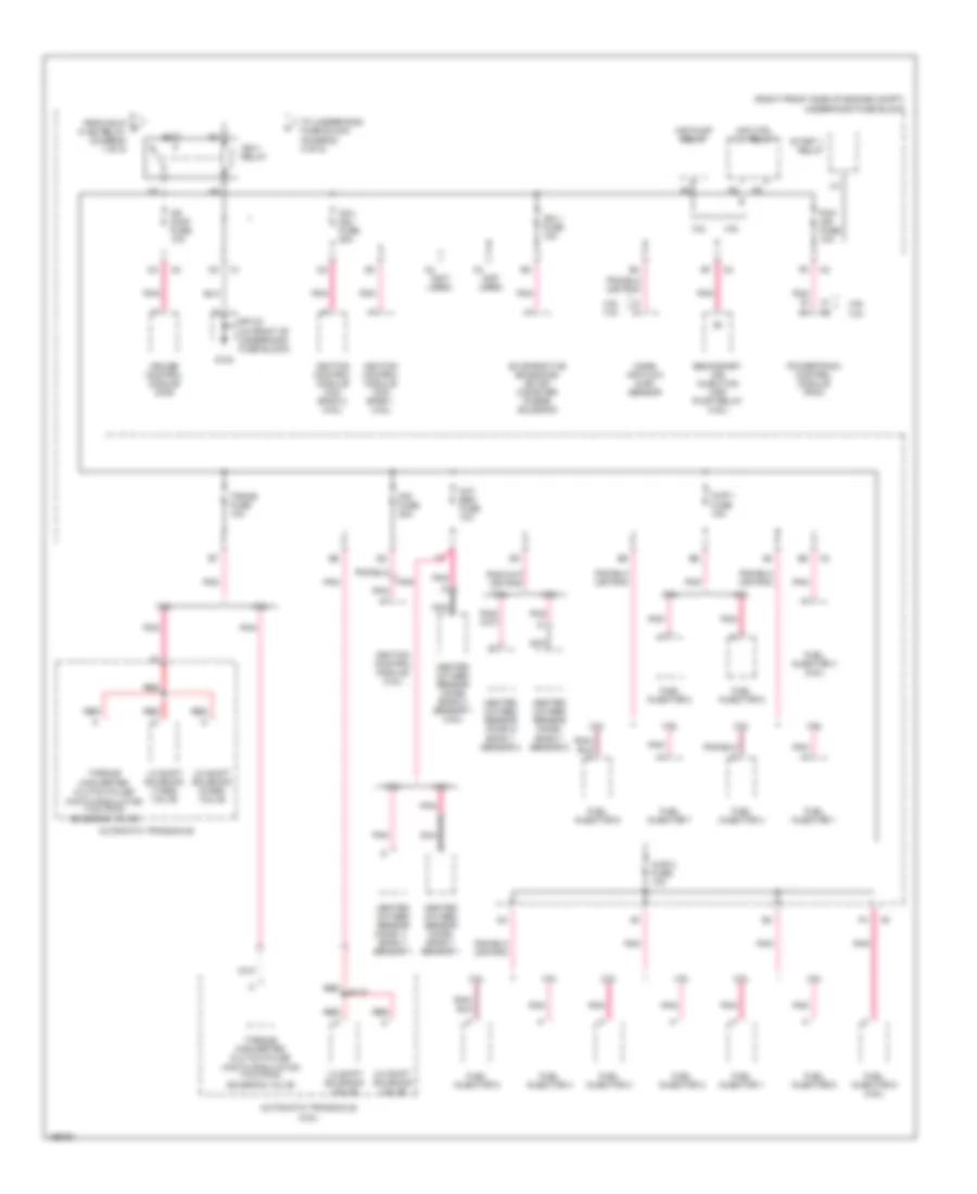
Power Distribution Wiring Diagram (1 of 5) for Pontiac Bonneville GXP 2005

List of elements for Power Distribution Wiring Diagram (1 of 5) for Pontiac Bonneville GXP 2005:
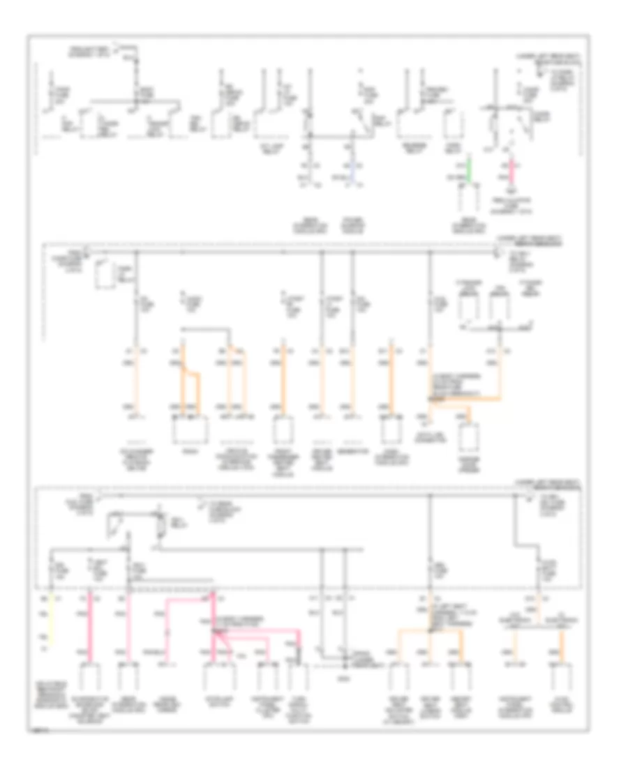
Power Distribution Wiring Diagram (2 of 5) for Pontiac Bonneville GXP 2005
List of elements for Power Distribution Wiring Diagram (2 of 5) for Pontiac Bonneville GXP 2005:
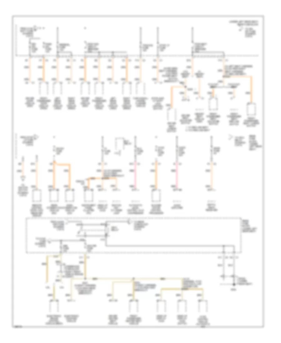
Power Distribution Wiring Diagram (3 of 5) for Pontiac Bonneville GXP 2005
List of elements for Power Distribution Wiring Diagram (3 of 5) for Pontiac Bonneville GXP 2005:
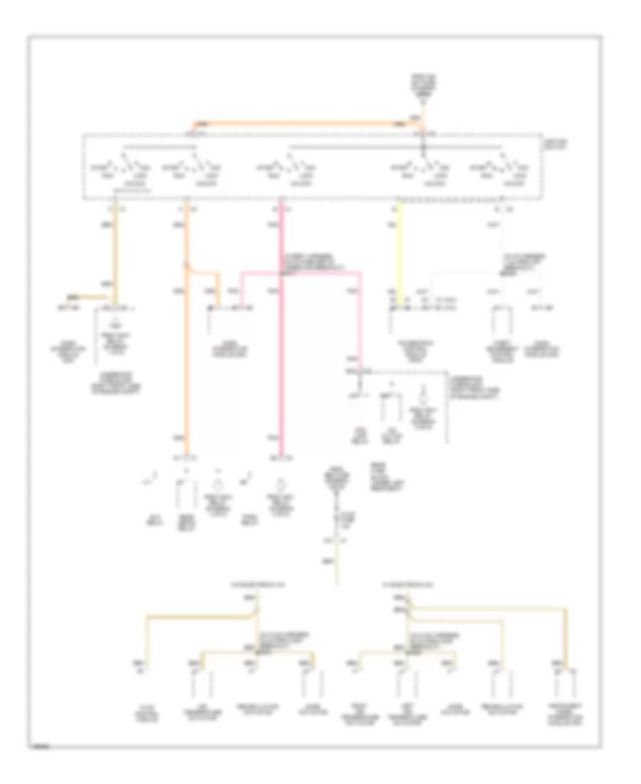
Power Distribution Wiring Diagram (4 of 5) for Pontiac Bonneville GXP 2005
List of elements for Power Distribution Wiring Diagram (4 of 5) for Pontiac Bonneville GXP 2005:
Power Distribution Wiring Diagram (5 of 5) for Pontiac Bonneville GXP 2005
List of elements for Power Distribution Wiring Diagram (5 of 5) for Pontiac Bonneville GXP 2005: