POWER DISTRIBUTION
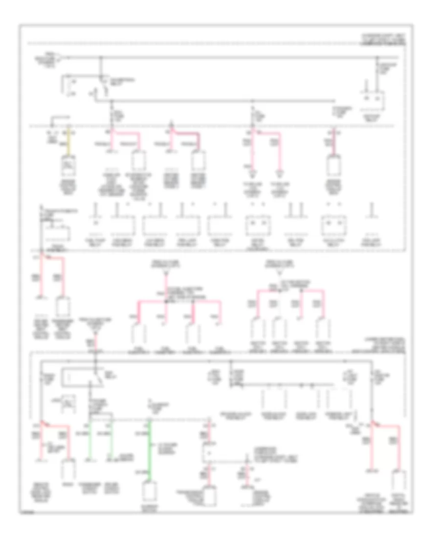
Power Distribution Wiring Diagram (1 of 3) for Pontiac G5 GT 2008

List of elements for Power Distribution Wiring Diagram (1 of 3) for Pontiac G5 GT 2008:
- (in engine compt, next to left strut tower) underhood fuse block
- + x1
- 50a
- A/t
- Abs 2 fuse 10a
- Abs 3 fuse 20a
- Abs fuse 40a
- Auxiliary power outlet
- Back up fuse 10a
- Back up lamp switch
- Bat (+)
- Battery
- Bcm2 fuse 40a
- Bcm3 fuse 30a
- Body control module (bcm) (under center dash, on right side of center console)
- Chmsl fuse 10a
- Chmsl relay
- Cigar lighter
- Cnstr vent fuse 10a
- Cooling fan 1 fuse 30a
- Cooling fan 1 relay
- Cooling fan 2 fuse 30a
- Cooling fan 2 relay
- Crank fuse 30a
- Crank relay
- D10 x3
- Data link connector (dlc)
- Dlc fuse 15a
- E6 (not used)
- Ecm/ trans fuse 15a
- Electronic brake control module (ebcm)
- Engine control module (ecm)
- Eps fuse 60a
- Evaporative emission (evap) canister vent solenoid valve
- Fusible link
- G101 (left side of engine compartment, under coolant reservoir)
- G203 (behind right side of dash)
- G301 (under driver's seat)
- Generator
- Hvac relay
- If equipped
- Inflatable restraint sensing & diagnostic module (sdm)
- Inline fuse
- Ip ign fuse 20a
- Mir/ ugdo fuse 5a
- Outlet fuse 20a
- Outside rearview mirror switch
- Pnk
- Power steering control module (pscm)
- Rear defog fuse 40a
- Rear defog relay
- Red
- Run/ crank relay
- Run/ crank relay coil ctrl
- Sdm fuse 10a
- Starter
- To body control module (diagram 2 of 3)
- To body control module (diagram 3 of 3)
- To power- train relay (diagram 2 of 3)
- Transmission control module (tcm)
- W/ active brake
- W/o active brake
- Wiper fuse 25a
- Wpr lo/hi relay
- Wpr on/off relay
- X1 f5
- X3 b2
- X3 c5
- X4 b1
- X4 c2
- X5 a2
- X5 a5
- X5 b2
- X5 b3
- X5 d5
- X5 e5
- X6 a
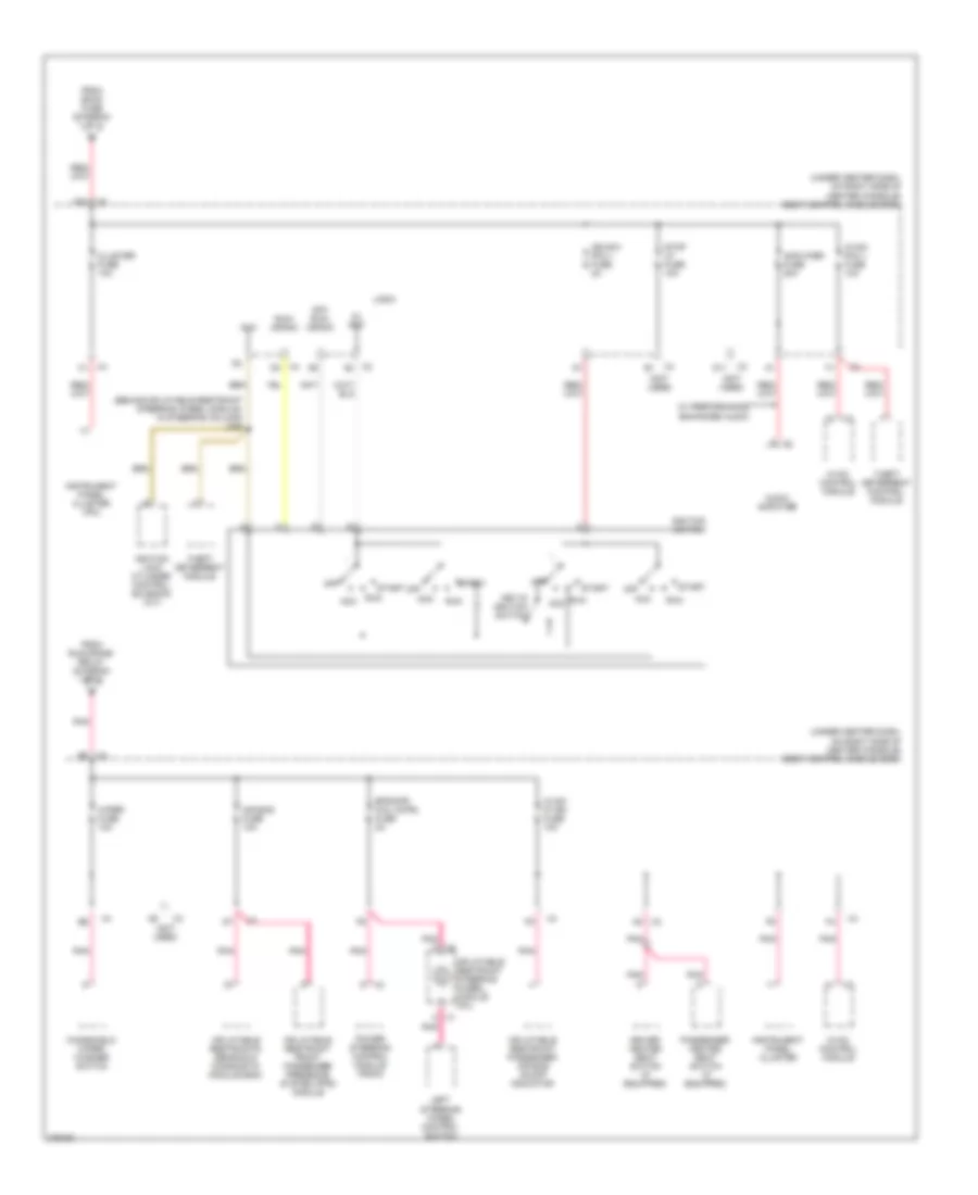
Power Distribution Wiring Diagram (2 of 3) for Pontiac G5 GT 2008
List of elements for Power Distribution Wiring Diagram (2 of 3) for Pontiac G5 GT 2008:
- (coupe) (sedan)
- (in engine compt, next to left strut tower) underhood fuse block
- (in fuel injectors harness, top, pnk
- (in the ignition coil harness) j141
- (not used)
- (under center dash, on right side of center console) body control module (bcm)
- A/c clutch relay
- A2 x1
- Air pump fuse 40a
- Air pump relay
- Air sol relay (2.2l/sulev)
- C11
- D1 x3
- D10
- Digital radio receiver (if equipped)
- Door lock fuse 15a
- Door lock pcb relay
- Door unlock pcb relay
- Dr door unlock pcb relay
- Driver heated seat control module
- Driver window switch
- Drl pcb relay
- E x2
- E10 (not used)
- E3 x5
- E4 x5
- Ecm/ tcm fuse 10a
- Engine control module (ecm)
- Evaporative emission (evap) canister purge solenoid valve
- Exh fuse 10a
- Fog lamp pcb relay
- From bcm3 fuse c (diagram 1 of 3)
- From inj fuse (diagram 2 of 3)
- From inline fuse (diagram 1 of 3)
- Fuel injector 1
- Fuel injector 2
- Fuel injector 3
- Fuel injector 4
- Fuel pump relay
- Heated oxygen sensor (ho2s) 1
- Heated oxygen sensor (ho2s) 2
- High beam pcb relay
- Horn pcb relay
- Ignition coil/ module 1
- Ignition coil/ module 2
- Ignition coil/ module 3
- Ignition coil/ module 4
- Inj fuse 15a
- Int light fuse 10a
- Interior light pcb relay
- Left side of engine) j103
- Logic
- Low beam pcb relay
- M/t
- Mass air flow (maf)/ intake air temperature (iat) sensor
- Passenger heated seat control module
- Passenger window switch
- Pcm/ecm fuse 15a
- Pnk
- Power window fuse 30a
- Powertrain relay
- Prk lamp pcb relay
- Radio
- Radio fuse 15a
- Rap relay
- Remote control door lock receiver (rcdlr)
- Rly ctrl
- Sunroof fuse 15a
- Sunroof switch
- To splice j103 (diagram 2 of 3)
- To splice j141 (diagram 2 of 3)
- Transmission control module (tcm)
- Trunk pcb relay
- Trunk/htd seats fuse 20a
- Underhood fuse block (in engine compt, next to left strut tower)
- Vehicle communication interface module (vcim) (if equipped)
- W/ keyless entry
- W/ power sliding sunroof
- X1 f6
- X3 d4
- X5 b1
- X5 e2
- Xm/ onstar fuse 10a
Power Distribution Wiring Diagram (3 of 3) for Pontiac G5 GT 2008
List of elements for Power Distribution Wiring Diagram (3 of 3) for Pontiac G5 GT 2008:
- (behind inflatable restraint steering wheel module, in steering column) j206
- (not used)
- (under center dash, on right side of center console) body control module (bcm)
- 5v ref
- A4 x2
- A8 x3
- Acc
- Air bag fuse 10a
- Amplifier fuse 20a
- Audio amplifier
- Cluster fuse 10a
- D11
- D12 x3
- Driver heated seat switch (if equipped)
- Eps/str whl cntrl fuse 2a
- From bcm2 fuse (diagram 1 of 3)
- From run/crank relay (diagram 1 of 3)
- Hvac control module
- Hvac/ ip ign fuse 10a
- Hvac/ pk3 + fuse 10a
- Ign sw/ pk3 + fuse 2a
- Ignition lock cylinder control solenoid (a/t)
- Ignition switch
- Inflatable restraint front passenger presence system (pps) module
- Inflatable restraint passenger air bag on/off indicator
- Inflatable restraint steering wheel module coil
- Inflatable restraints sensing & diagnostic module (sdm)
- Instrument panel cluster
- Instrument panel cluster (ipc)
- Key-in ignition switch
- Left steering wheel control switch
- Logic
- Off
- Off/ run/ crank
- Passenger heated seat switch (if equipped)
- Pnk
- Pnk c
- Pnk d
- Power steering control module (pscm)
- Run
- Run/ crank
- Start
- Stop lp fuse 10a
- Theft deterrent control module
- Theft deterrent module
- W/ performance enhanced audio
- Windshield wiper/ washer switch
- Wiper fuse 10a
- X1 c pnk
- X2 a1
- X3 d6
- X4 c1
- X4 d3