POWER DISTRIBUTION
Power Distribution Wiring Diagram (1 of 3) for Pontiac Grand Prix GT 2004

List of elements for Power Distribution Wiring Diagram (1 of 3) for Pontiac Grand Prix GT 2004:
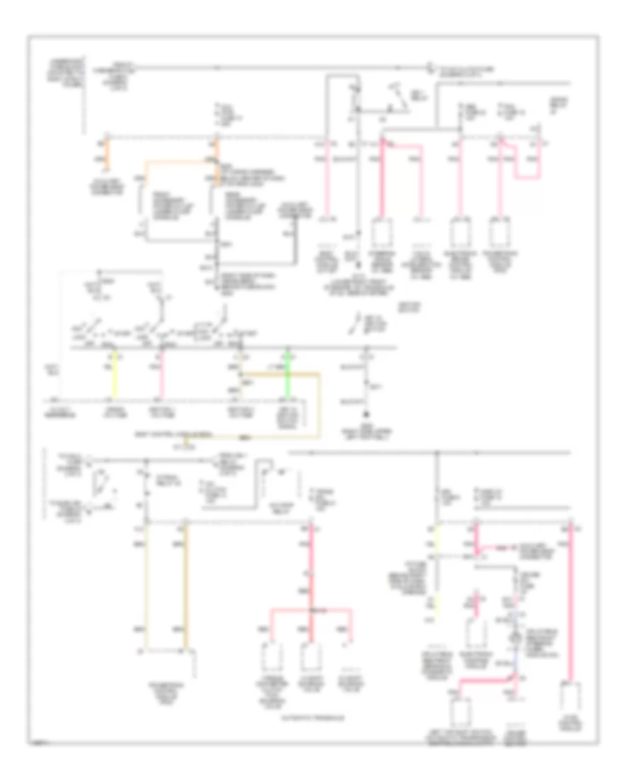
Power Distribution Wiring Diagram (2 of 3) for Pontiac Grand Prix GT 2004
List of elements for Power Distribution Wiring Diagram (2 of 3) for Pontiac Grand Prix GT 2004:
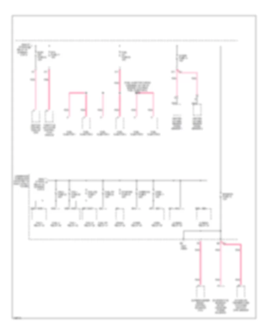
Power Distribution Wiring Diagram (3 of 3) for Pontiac Grand Prix GT 2004
List of elements for Power Distribution Wiring Diagram (3 of 3) for Pontiac Grand Prix GT 2004: