POWER DISTRIBUTION
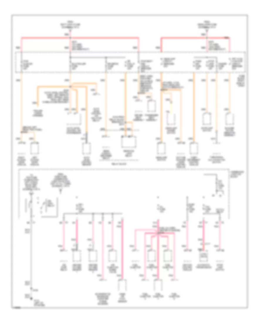
Power Distribution Wiring Diagram (1 of 4) for Pontiac Montana 2001

List of elements for Power Distribution Wiring Diagram (1 of 4) for Pontiac Montana 2001:
- (body harn, left rear wheelwell) s326
- (diagram 1 of 4)
- (diagram 2 of 4)
- (diagram 3 of 4)
- (i/p harn, 21cm from from radio breakout)
- (i/p harn, 80cm from the cigar lighter connector)
- Air pump fuse 30a
- Air pump relay
- Alt/ sense fuse 10a
- B/u lamp fuse 10a
- Batt main 1 fuse 60a
- Batt main 2 fuse 60a
- Battery
- Body control module
- Cigar lighter
- Cigar/dlc/ apo frt fuse 15a
- Cluster batt fuse 10a
- Cool fan 1 fuse 30a
- Cool fan 1 relay
- Cool fan 2 fuse 30a
- Cool fan 2 relay
- Cool fan relay
- Ctsy lamp fuse 10a
- Data link connector
- Daytime running lamps control module
- Driver information center (dic)
- E12
- E16
- Ecm sense fuse 10a
- Electronic brake control module
- Fog lamp relay
- Fog lp fuse 10a
- From radio fuse a
- Front auxiliary power outlet
- Fuel pump fuse 15a
- Fuel pump relay
- Fuse block (right side of dash)
- Fusible link a (10ga-rust)
- G201 (right side of dash, left of heater-a/c vent)
- Generator
- Head- lamps fuse 60a
- Headlamp switch
- Horn fuse 15a
- Horn relay
- Hvac control module
- Ign main 1 fuse 40a
- Ign main 2 fuse 60a
- Ign main relay (diagram 2 of 4)
- Instrument panel cluster (ipc)
- Left sliding door module
- Onstar fuse 10a
- Outside rearview mirror switch
- Park lp fuse 20a
- Powertrain control module
- Pwr lock fuse 20a
- Pwr mirror fuse 10a
- Radio
- Radio fuse 10a
- Rap relay fuse 10a
- Rear auxiliary power outlet
- Red
- Remote control door lock receiver
- Right sliding door module
- Rr pwr sckt fuse 20a
- S202
- S212
- S213
- S238
- S276 (i/p harn, 8cm from bcm breakout)
- Shock sensor
- Starter
- Starter relay
- Theft led
- To cool fan 1 fuse (diagram 1 of 4)
- To ignition switch pin d2
- To ignition switch pin d5
- To rap relay (diagram 4 of 4)
- To s274
- To s278
- Transaxle range switch
- Underhood junction block
- Vehicle interface unit (viu)
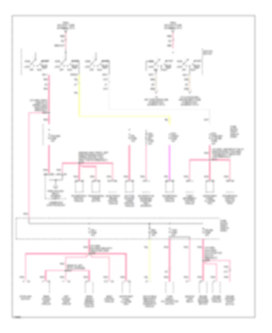
Power Distribution Wiring Diagram (2 of 4) for Pontiac Montana 2001
List of elements for Power Distribution Wiring Diagram (2 of 4) for Pontiac Montana 2001:
- (6 cm from relay block breakout) s270
- (behind left rear trim panel) s322
- (body harn, 34cm from inflatable restraint sensing & diagnostic module) s302
- (diagram 1 of 4)
- (fuel inj harn, center of engine) s109
- (i/p harn, 13 cm from headlamp switch breakout) s215
- A/c clu fuse 10a
- A/c clu relay
- A12
- Air injection bleed valve
- Air pump relay
- Auto level control air compressor
- Auto level control air inflator relay
- Auto level control sensor
- Automatic transmission
- Blower motor resistor assembly
- C111
- Ctrl sols
- Daytime running lamps control module
- Driver seat assembly
- Elc/trailer fuse 25a
- Elek ign fuse 15a
- Evaporative emissions canister purge solenoid
- From batt main 2 fuse
- From headlamps fuse
- From horn fuse (underhood junction block) (hot at all times) (diagram 1 of 4)
- Frt hvac hi blowr circuit breaker 30a
- Fuel injector
- Fuse block (right side of dash)
- G110 (left of starter)
- Hazard fuse 15a
- Headlamp circuit breaker 20a
- Headlamp dimmer switch
- Headlamp switch
- Heated oxygen sensor
- Ign i- u/h fuse 15a
- Ign main relay
- Ignition control module
- Inj fuse 10a
- Left sliding door module
- Mass air flow sensor
- Nca
- Pass key fuse 10a
- Passenger seat assembly
- Pnk
- Pwr seat/ psd circuit breaker 30a
- Pwr sldg dr fuse 30a
- Rear fog lamp relay
- Rear window defogger relay
- Red
- Relay block
- Right sliding door module
- Rr defog fuse 30a
- Rr fog lp fuse 30a
- S106
- S274 (i/p harn, 4cm from bcm breakout)
- S278 (i/p harn, 12cm from bcm breakout)
- S445 (auto level control harn, left rear of body approx 16cm from left rear wheelhouse grommet)
- Stop lamp fuse 15a
- Stop- lamp switch
- Stoplamp switch
- Tcc fuse 10a
- Theft deterrent control module
- To pcm fuse (fuse block) (hot in run, bulb test or start) (diagram 3 of 4)
- Trailer wiring harness
- Turn/signal multifunction switch
- Underhood junction block
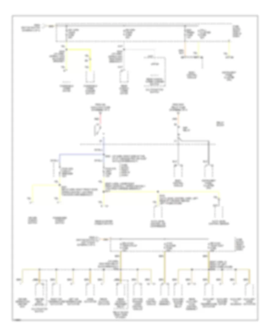
Power Distribution Wiring Diagram (3 of 4) for Pontiac Montana 2001
List of elements for Power Distribution Wiring Diagram (3 of 4) for Pontiac Montana 2001:
- (engine harn, front left side of engine compt approxiamately 8cm from the pcm breakout) s108
- (i/p harn, 24cm from multifunction switch breakout) s266
- (i/p harn, center of the i/p aproxiamately 4cm from the security indicator lamp breakout) s210
- (i/p harn, pnk 8cm from security indicator lamp) s209
- (i/p harn, right side of i/p approx 25cm from radio breakout) s228
- (rear of left "b" pillar base) s337
- A11
- A13
- Acc
- Acc 1
- Backup lamp relay
- Body control module
- Bulb test
- C10
- C13
- Can vent sol fuse 10a
- Crank
- Cruise control module
- Cruise control on/off switch
- Cruise control release switch
- Cruise fuse 10a
- D11
- Daytime running lamps control module
- Drl fuse 10a
- Electronic brake control module
- Evaporative emissions canister vent solenoid
- From ign main 1 fuse (diagram 1 of 4)
- From ign main 2 fuse (diagram 1 of 4)
- From ign main relay (diagram 2 of 4)
- Fuse block (right side of dash)
- Ign 0
- Ign 1
- Ign 1 fuse 10a
- Ign 3
- Ignition switch
- Inflatable restraint sensing & diagnostic module
- Instrument panel cluster (ipc)
- Left sliding door module
- Lock
- Off
- Pcm/ crank fuse 10a
- Pcm/ pass key/ cluster fuse 10a
- Pcm/abs fuse 10a
- Pnk
- Powertrain control module
- Powertrain control module (pcm)
- Rear object sensor control module
- Rear sliding door module
- Red
- Run
- Sdm fuse 15a
- Start
- Stoplamp switch
- T/sig fuse 10a
- Theft deterrent control module
- To frt wpr/wshr fuse (fuse block) (diagram 4 of 4)
- To hvac/dic/drl/ heated seat fuse (fuse block) (diagram 4 of 4)
- Transmission range switch
- Turn signal/ multifunction switch
- Underhood junction block
Power Distribution Wiring Diagram (4 of 4) for Pontiac Montana 2001
List of elements for Power Distribution Wiring Diagram (4 of 4) for Pontiac Montana 2001:
- (body harn, in front of left rear wheelhouse) s345
- (body harn, under right front door sill, approxiamately 17cm from harness breakout) s317
- (diagram 3 of 4)
- (i/p harn, 16cm from relay block breakout) s264
- (i/p harn, right side of the i/p at the electric air inlet actuator breakout)
- Auto level control air compressor
- Auto level control sensor
- Auxiliary air temperature actuator
- Auxiliary blower motor
- Auxiliary blower motor relay
- Auxiliary mode actuator
- Auxiliary txv solenoid
- Bcm prgrm fuse 10a
- Body control module
- Daytime running lamps control module
- Driver information center (dic)
- Driver window switch
- Drl/hvac/ temp/htd st fuse 10a
- From ign main 2 maxi fuse (diagram 1 of 4)
- From ignition switch
- From ignition switch j (hot in run) (diagram 3 of 4)
- From rap relay fuse (diagram 1 of 4)
- Frt wpr/ wshr fuse 25a
- Fuse block (right side of dash)
- Heated seat switch
- Hvac blower fuse 25a
- Hvac control assembly
- Hvac control module
- Instrument panel cluster (ipc)
- Left air temperature actuator
- Mall/ cluster fuse 10a
- Mode actuator
- Multifunction switch
- Multifuntion switch
- Nca
- Passenger window switch
- Pwr otr vent fuse 10a
- Pwr wdo circuit breaker 30a
- Rap relay
- Rear auxiliary hvac control assembly
- Rear quarter window switch
- Rear window defogger relay
- Rear window wiper motor
- Rear window wiper/ washer switch
- Recir- culation actuator
- Red
- Relay block
- Relay block (right side of dash)
- Right air temperature actuator
- Rr hvac/ te;mp cont fuse 25a
- Rr wpr/ wshr fuse 20a
- S245 (i/p harn, approx 5cm from radio breakout)
- S249 (i/p harn, approx 14cm bulkhead grommet)
- S263
- S307 (boyd harn, right front door approxiamately 4cm from the door harn breakout)
- S440 (auto level control harn, left rear of the body behind left wheelhouse)
- Windshield wiper motor
- Windshield wiper/ washer switch