POWER DISTRIBUTION
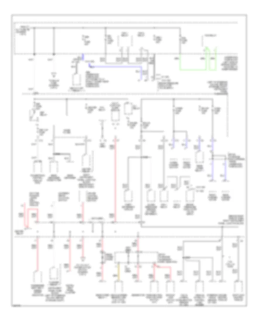
Power Distribution Wiring Diagram (1 of 4) for Pontiac Vibe 2006

List of elements for Power Distribution Wiring Diagram (1 of 4) for Pontiac Vibe 2006:
- (not used)
- Air pump fuse 50a
- Air pump relay (1.8l (vin l))
- Alt fuse 100a
- Alt s fuse 5a
- Am 2 fuse 15a
- Amp fuse 30a
- Battery
- C13
- Cd changer
- Digital radio receiver
- Dome fuse 15a
- Efi fuse 15a
- Efi relay
- Etc s fuse 10a
- Flasher relay
- From head main a
- Front dome lamp
- Fuse (diagram 1 of 4)
- Generator
- Hazard fuse 10a
- Head main fuse 30a
- Head relay
- Horn fuse 10a
- Horn relay
- Instrument panel cluster
- Instrument panel fuse block (left of steering column, behind storage compt)
- Keyless entry module
- Left instrument panel junction block (behind left side of dash)
- Main fuse 30a
- Map lamp
- Mayday onstar fuse 10a
- Module (vcim)
- Nca
- Powertrain control module (pcm)
- Powertrain control module (pcm) (1.8l (vin 8), fwd)
- Radio
- Radio amplifier
- Rear dome lamp
- Red
- S234
- S300
- St relay
- Starter
- Sunroof switch
- To abs 2 fuse (diagram 2 of 4)
- To horn fuse (diagram 1 of 4)
- To ignition switch (diagram 4 of 4)
- Underhood fuse block (left side of engine compt, mounted to inner fender)
- Vehicle communication interface
- Vehicle interface unit (viu)
- W/ sunroof
- W/o sunroof
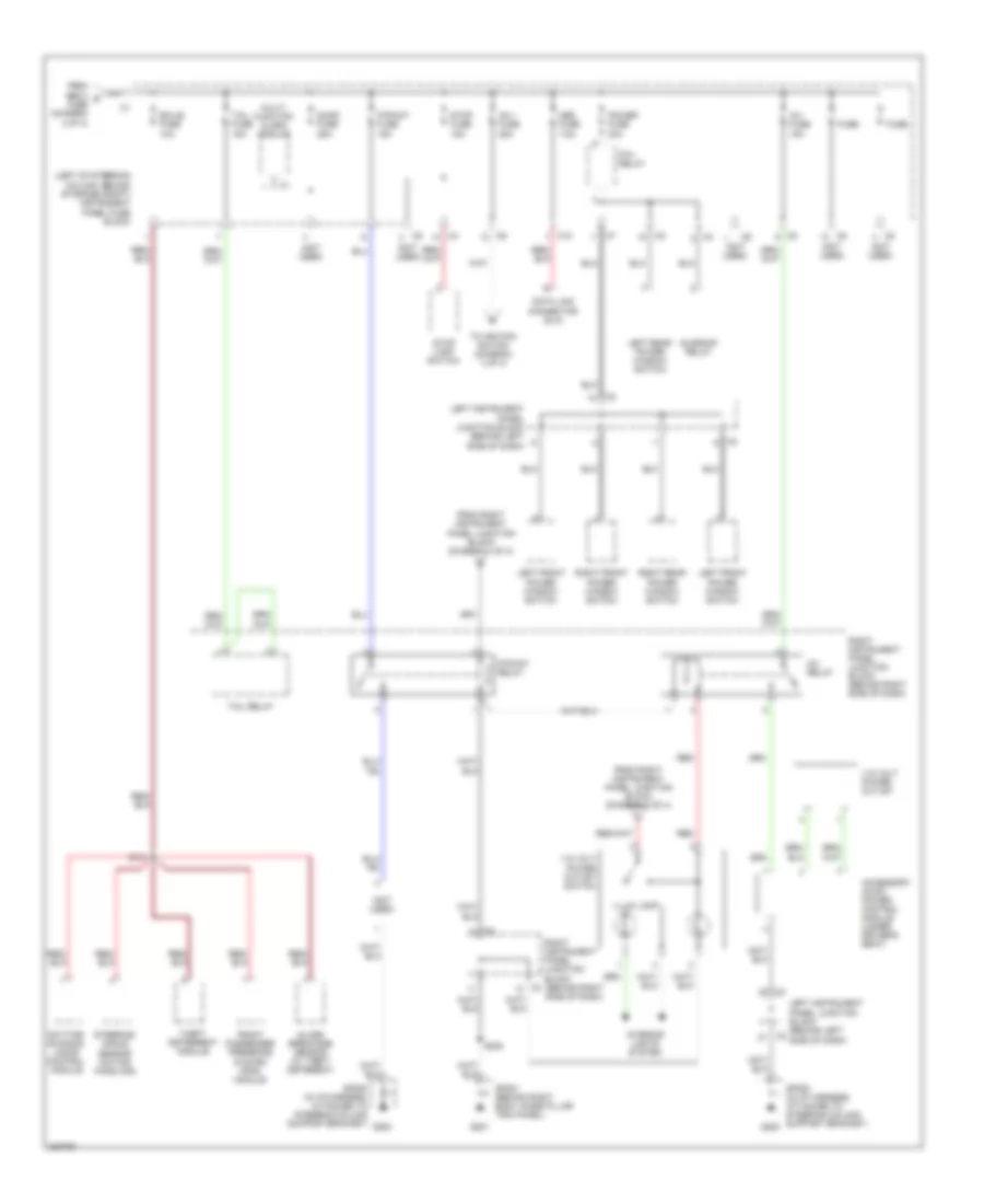
Power Distribution Wiring Diagram (2 of 4) for Pontiac Vibe 2006
List of elements for Power Distribution Wiring Diagram (2 of 4) for Pontiac Vibe 2006:
- (1.8l (vin l) & awd)
- (behind right side of dash) right instrument panel junction block
- (diagram 1 of 4)
- (left of steering column, behind storage compt) instrument panel fuse block
- (not used)
- Abs 1 fuse 30a
- Abs cut off relay
- Abs fuse 40a
- Abs underhood fuse block (attached to lf strut tower, near underhood fuse block)
- Ac/fresh/ recir- culation switch
- Backup lamp switch (m/t)
- Brake pressure modulator valve (bpmv)
- C12
- C13
- Cruise control module
- Cruise control release switch
- Daytime running lamps (drl) control module
- Def fuse 30a
- Def i/up fuse 10a
- Def relay
- Ecu-ig fuse 10a
- Fan 1 relay
- Fan 2 relay
- Flasher relay
- Fog fuse 15a
- Fog relay
- From alt fuse b
- Front washer motor
- Front wiper motor
- Gauge fuse 10a
- Generator
- Glass breakage sensor (w/ theft deterent)
- Heater fuse 40a
- Heater relay
- Ig 1 relay
- Instru- ment panel cluster
- Instrument panel fuse block (left of steering column, behind storage compt)
- Multi- function alarm module
- Noise filter
- P/w relay
- Park/neutral position (pnp) switch (a/t)
- Passenger seat belt/ airbag on/off indicator
- Powertrain control module (pcm)
- Rdi fan fuse 40a
- Rear defogger
- Rear defogger noise filter
- Rear washer motor
- Rear wiper diode
- Rear wiper relay 1
- Right instrument panel junction block (behind right side of dash)
- Rr wip fuse 15a
- S122
- S230
- S302
- Shiftlock control module
- Sp107 (in engine accessory harn, near pcm)
- Sp109 (in engine main harness, inside underhood fuse block)
- Steering angle sensor (w/ vsc)
- Theft deterrent module
- To 115 volt power outlet switch (diagram 3 of 4)
- To ecu b fuse (diagram 3 of 4)
- Underhood fuse block (left side of engine compt, mounted to inner fender)
- Vehicle speed sensor (vss) (1.8l (vin 8), 2wd, w/ vsc)
- Vehicle stability control (vsc) buzzer
- W/ vsc
- W/o vsc
- Wash fuse 15a
- Wiper fuse 25a
- Wiper/ washer switch
- Yaw & lateral acceleration sensor (w/ vsc)
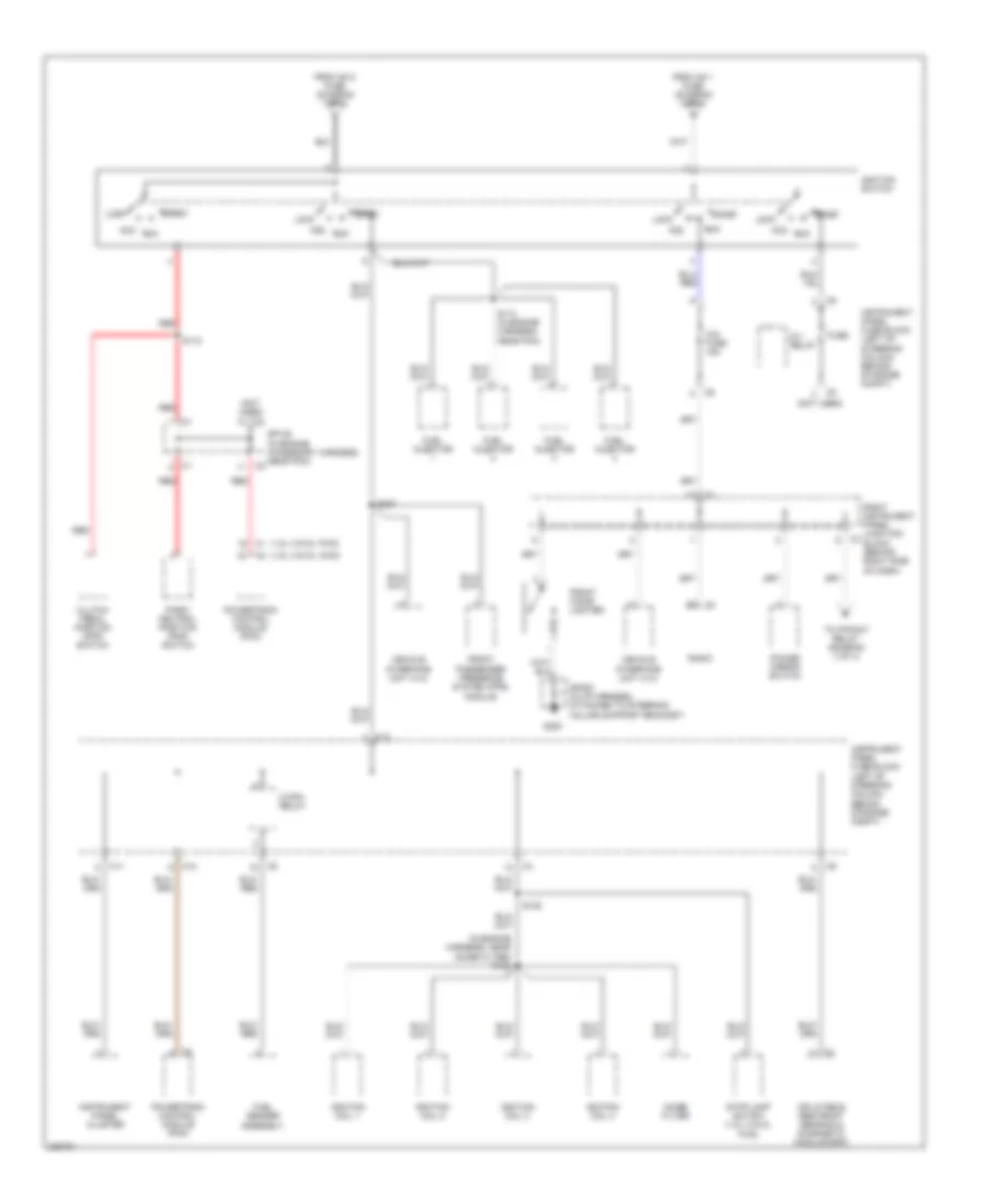
Power Distribution Wiring Diagram (3 of 4) for Pontiac Vibe 2006
List of elements for Power Distribution Wiring Diagram (3 of 4) for Pontiac Vibe 2006:
- (left of steering column, behind storage compt) instrument panel fuse block
- (not used)
- 115 volt power outlet
- 115 volt power outlet switch
- Accessory ac/dc power control module (under driver's seat)
- Am 1 fuse 25a
- C10
- Data link connector (dlc)
- Daytime running lamps control module
- Door fuse 25a
- Ecu-b fuse 10a
- From abs 2 d fuse (diagram 2 of 4)
- From right instrument panel junction block (diagram 2 of 4)
- From right instrument panel junction block (diagram 4 of 4)
- Front passenger presence system (pps) module
- Fuse
- G200
- G201
- Glass breakage sensor (w/ theft deterent)
- Illum lamp
- Interior lights system
- Inv fuse 15a
- Inv relay
- Left front power window switch
- Left instrument panel junction block (behind left side of dash)
- Left rear power window switch
- Multi- function alarm module
- Obd fuse 7.5a
- P/point fuse 15a
- P/point relay
- P/w relay
- Power fuse 30a
- Red
- Right front power window switch
- Right instrument panel junction block (behind right side of dash)
- Right rear power window switch
- S121
- S222
- Sp200 (in i/p harness, attached to steering column support bracket)
- Sp201 (behind right body hinge pillar trim panel)
- Steering angle sensor (actice handling)
- Stop fuse 15a
- Stop lamp switch
- Sunroof relay
- Tail fuse 15a
- Tail relay
- Theft deterrent module
- To ignition switch (diagram 4 of 4)
Power Distribution Wiring Diagram (4 of 4) for Pontiac Vibe 2006
List of elements for Power Distribution Wiring Diagram (4 of 4) for Pontiac Vibe 2006:
- (1.8l (vin 8), awd) c2
- (1.8l (vin 8), fwd) c1
- (in engine harness, near noise filter) s106
- (not used)
- Acc
- C/opn relay
- C1 b2
- C11
- C12
- Cig fuse 15a
- Clutch pedal position (cpp) switch
- From am 1 fuse (diagram 3 of 4)
- From am 2 fuse (diagram 1 of 4)
- Front cigar lighter
- Front passenger presence system (pps) module
- Fuel injector
- Fuel sender assembly
- Fuse
- G200
- Ig 1 relay
- Ignition coil 1
- Ignition coil 2
- Ignition coil 3
- Ignition coil 4
- Ignition switch
- Inflatable restraint sensing & diagnostic module (sdm)
- Instrument panel cluster
- Instrument panel fuse block (left of steering column, behind storage compt)
- Lock
- Noise filter
- Park/ neutral position (pnp) switch
- Power mirror switch
- Powertrain control module (pcm)
- Radio
- Red
- Right instrument panel junction block (behind right side of dash)
- Run
- S110
- S114 (in engine harness, near pcm)
- S125
- S237
- Sp108 (in engine accessory harness, near pcm)
- Sp200 (in i/p harness, attached to steering column support bracket)
- Start
- Stop lamp switch (1.8l (vin 8), fwd)
- To p/point relay (diagram 3 of 4)
- Vehicle interface unit (viu)