POWER DISTRIBUTION
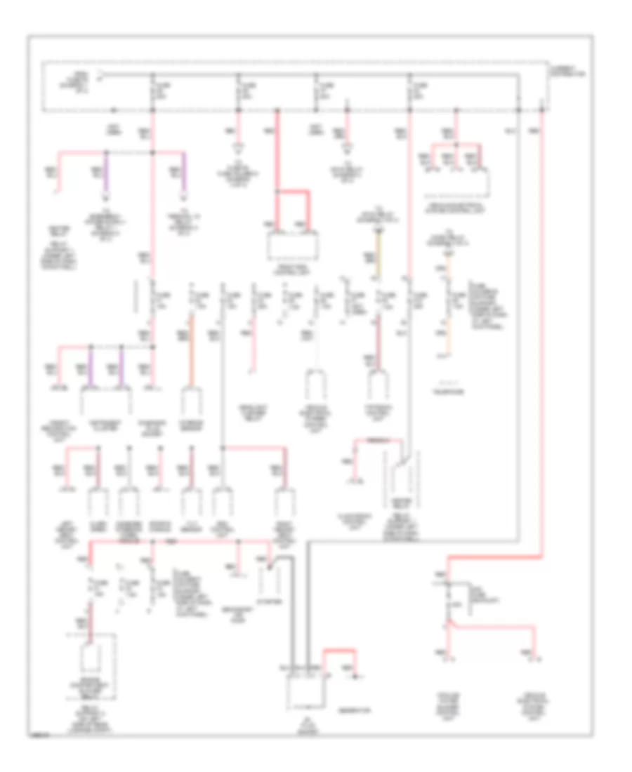
Power Distribution Wiring Diagram (1 of 4) for Porsche Cayman 2008

List of elements for Power Distribution Wiring Diagram (1 of 4) for Porsche Cayman 2008:
- (not used)
- Battery
- Cigar lighter
- Convertible top closed relay (convertible)
- Convertible top open relay (convertible)
- Current distributor
- Driver door control unit
- Front end control unit
- Fuse e1 30a
- Fuse e2 30a
- Fuse e3 30a
- Fuse e4 (not used)
- Fuse f1 30a
- Fuse f1 80a
- Fuse f10 15a
- Fuse f2 15a
- Fuse f3 15a
- Fuse f3 70a
- Fuse f4 150a
- Fuse f4 30a
- Fuse f5 15a
- Fuse f5 50a
- Fuse f6 15a
- Fuse f7 15a
- Fuse f8 7.5a
- Fuse f8 70a
- Fuse f9 25a
- Fuse holder a (on fuse support, under left side of dash, at left kick panel)
- Fuse holder e (on fuse support, under left side of dash, at left kick panel)
- Gp4 (at center of dash)
- Gp5 (right side of dash)
- Interior lights system
- Left comfort power seat switch
- Left power seat control unit
- Left seat width adjustment switch
- Package tray plug socket
- Passenger door control unit
- Plug socket 2
- Psm control unit
- Rear control unit
- Rear window defogger relay
- Red
- Red b
- Red c
- Right comfort power seat switch
- Right seat width adjustment switch
- To fuse f1 fuse holder d (diagram 4 of 4)
- To fuse f6 (diagram 2 of 4)
- Vehicle electrical system control unit
- W/ memory
- W/o memory
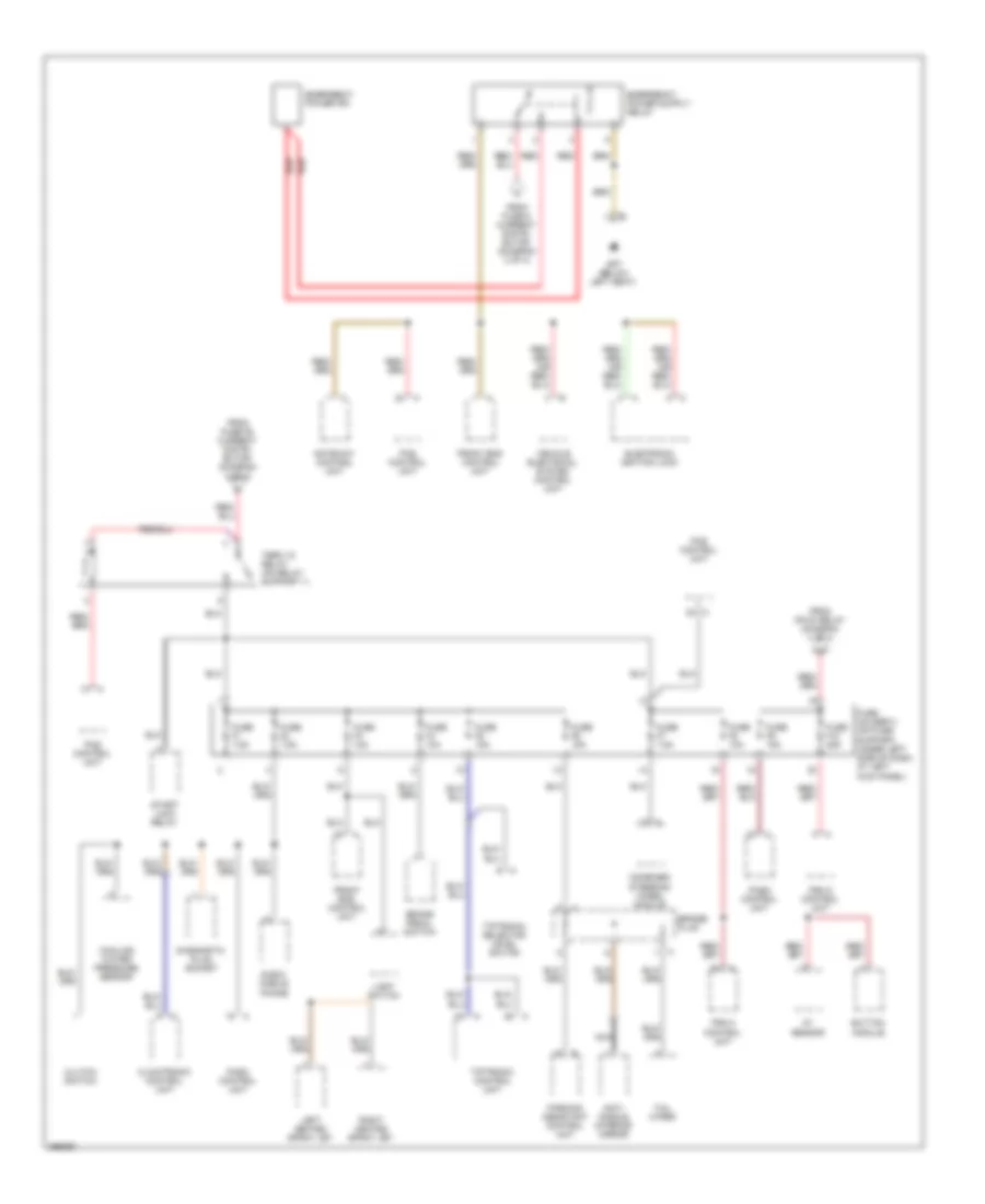
Power Distribution Wiring Diagram (2 of 4) for Porsche Cayman 2008
List of elements for Power Distribution Wiring Diagram (2 of 4) for Porsche Cayman 2008:
- (not used)
- 80a
- A14
- Alarm siren
- B+ plug socket
- Climatronic control unit
- Combined steering wheel module
- Cooling water blower control unit
- Current distributor
- Diagnosis plug socket
- Engine compartment blower relay
- From fuse f5 (diagram 1 of 4)
- Front end control unit
- Fuse f1 15a
- Fuse f10 25a
- Fuse f2 7.5a
- Fuse f2 80a
- Fuse f3 15a
- Fuse f4 25a
- Fuse f5 7.5a
- Fuse f6 7.5a
- Fuse f6 80a
- Fuse f7 (not used)
- Fuse f7 80a
- Fuse f8 7.5a
- Fuse f9 7.5a
- Fuse f9 80a
- Fuse holder b (on fuse support, under left side of dash, at left kick panel)
- Fuse holder f (on fuse support, under left side of dash, at left kick panel)
- Generator
- Headlight cleaner relay
- Heater relay
- Instrument cluster
- Interior sensor
- Left memory seat control unit
- Midi fuse (exhaust)
- Rdk control unit
- Red
- Relay support 1 (under left side of dash, in footwell)
- Relay support 2 (on left side of rear luggage compt)
- Right memory seat control unit
- Secondary air pump
- Sports chrono
- Starter
- Telephone
- Tilt sensor
- Tiptronic control unit
- To fuse f9 fuse holder d (diagram 4 of 4)
- To mfi-di relay (diagram 4 of 4)
- To micro relay (diagram 4 of 4)
- To terminal 15 relay (diagram 3 of 4)
- Vehicle electrical sysrem control unit
- Vehicle electrical system control unit
- Weight recognition control unit
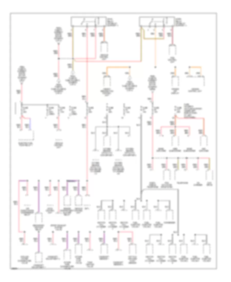
Power Distribution Wiring Diagram (3 of 4) for Porsche Cayman 2008
List of elements for Power Distribution Wiring Diagram (3 of 4) for Porsche Cayman 2008:
- Anti- dazzle interior mirror
- Ay sensor
- Brake pedal switch
- Bridge plug
- Button module
- Climatronic control unit
- Clutch switch
- Combined steering wheel module
- Cooling water pressure sensor
- Diagnostic plug socket
- E box mobile phone
- Electronic ignition lock
- Emergency power pin
- From fuse 6 current distri- butor (diagram 2 of 4)
- From fuse f6 current distri- butor (diagram 2 of 4)
- From mfi-di relay (diagram 4 of 4)
- Front end control unit
- Fuse f1 7.5a
- Fuse f10 25a
- Fuse f2 7.5a
- Fuse f3 10a
- Fuse f4 10a
- Fuse f5 15a
- Fuse f6 15a
- Fuse f7 7.5a
- Fuse f8 10a
- Fuse f9 15a
- Fuse holder c (on fuse support, under left side of dash, at left kick panel)
- Gateway control unit
- Gp7 (below left seat)
- Left heated spray jet
- Light switch
- Nca
- Parking assistant control unit
- Pas control unit
- Pasm control unit
- Psm 8 control unit
- Red
- Right heated spray jet
- Start lock relay
- Tail wiper
- Term 15 relay (on relay support 1)
- Tiptronic control unit
- Tiptronic selector level switch
- Vehicle electrical system control unit
Power Distribution Wiring Diagram (4 of 4) for Porsche Cayman 2008
List of elements for Power Distribution Wiring Diagram (4 of 4) for Porsche Cayman 2008:
- Air bag control unit
- Air bag off display
- Air conditioning compressor relay
- Ask amplifier
- Bose amplifier
- Bose subwoofer
- Camshaft adjustment 1
- Camshaft adjustment 2
- Camshaft sensor 1
- Camshaft sensor 2
- Cd changer
- Condenser
- Cooling water change-over valve
- Dmtl
- Dvd drive
- E box mobile telephone
- Electric fuel pump relay 1
- Engine compartment blower relay
- From fuse f4 current distri- butor (diagram 1 of 4)
- From fuse f7 current distri- butor (diagram 2 of 4)
- From fuse f8 fuse holder b (diagram 2 of 4)
- From fuse f9 current distri- butor (diagram 2 of 4)
- From fuse f9 fuse holder b (diagram 2 of 4)
- From fuse f9 fuse holder c (diagram 3 of 4)
- Fuel injector valve 1
- Fuel injector valve 2
- Fuel injector valve 3
- Fuel injector valve 4
- Fuel injector valve 5
- Fuel injector valve 6
- Fuse f1 25a
- Fuse f10 25a
- Fuse f2 (not used)
- Fuse f3 7.5a
- Fuse f4 (not used)
- Fuse f5 25a
- Fuse f6 25a
- Fuse f7 15a
- Fuse f8 7.5a
- Fuse f9 10a
- Fuse holder d (on fuse support, under left side of dash, at left kick panel)
- Hot film air mass flow sensor
- Ignition coil cylinder
- Intake pipe change-over valve
- Intake pipe flap valve
- Mfi-di control unit
- Mfi-di relay (on relay support 1)
- Micro relay (on relay support 1)
- N690 subwoofer
- Oxygen sensor catalytic converter 1
- Oxygen sensor catalytic converter 2
- Oxygen sensor catalytic converter cylinders 1-3
- Oxygen sensor catalytic converter cylinders 4-6
- Pas control unit
- Pcm actuator infosystem
- Red
- Secondary air pump relay
- Sport exhaust system valve
- Tank venting valve
- Telephone
- Vehicle control unit
- Weight recognition control unit