POWER DISTRIBUTION
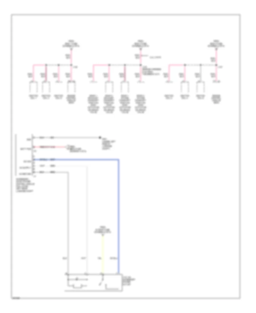
Power Distribution Wiring Diagram (1 of 5) for Saturn Vue Red Line 2009

List of elements for Power Distribution Wiring Diagram (1 of 5) for Saturn Vue Red Line 2009:
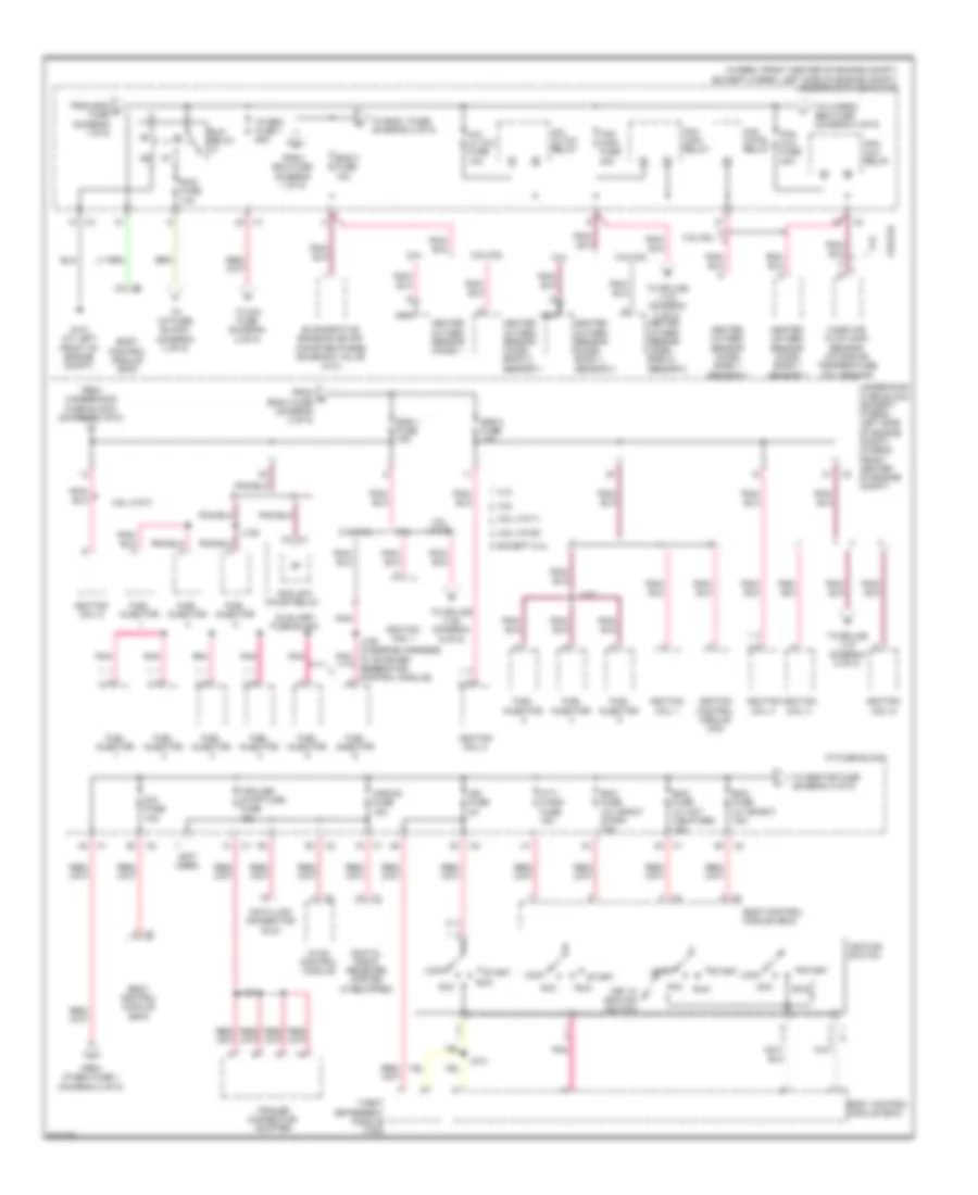
Power Distribution Wiring Diagram (2 of 5) for Saturn Vue Red Line 2009
List of elements for Power Distribution Wiring Diagram (2 of 5) for Saturn Vue Red Line 2009:
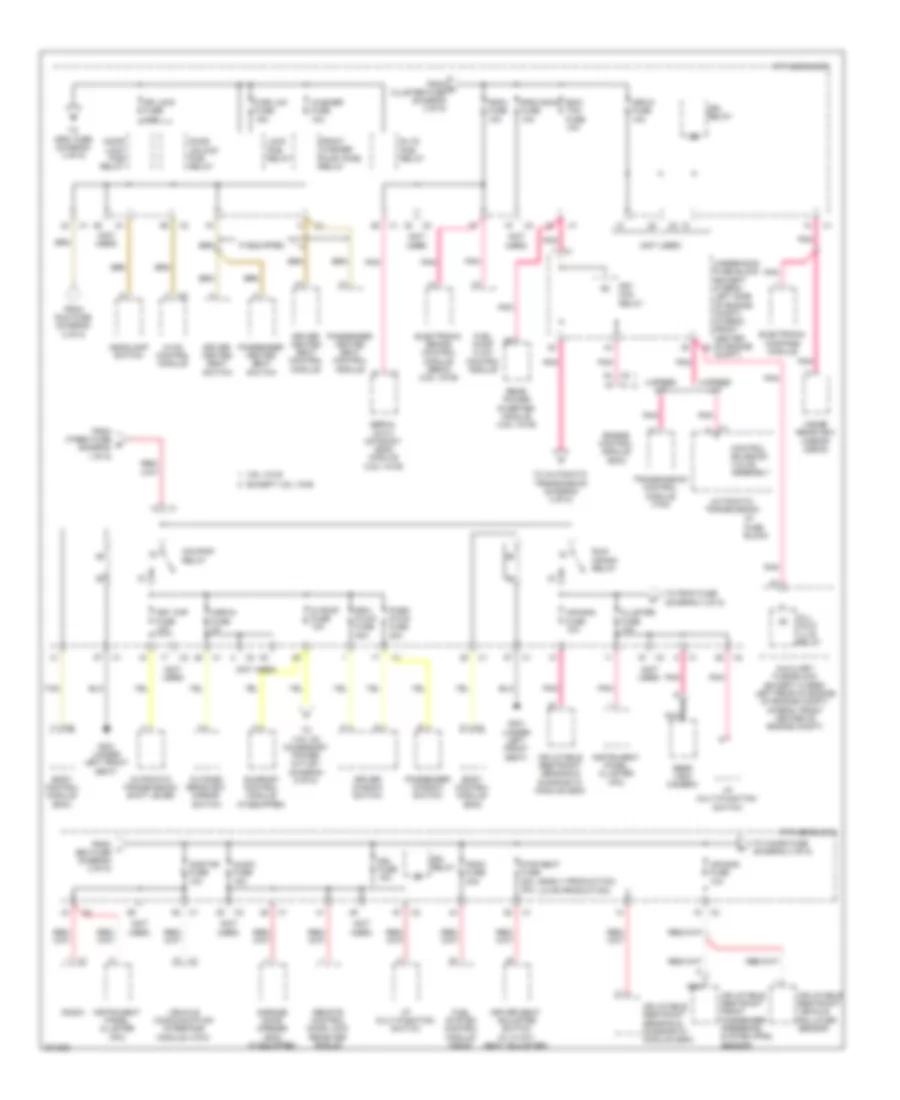
Power Distribution Wiring Diagram (3 of 5) for Saturn Vue Red Line 2009
List of elements for Power Distribution Wiring Diagram (3 of 5) for Saturn Vue Red Line 2009:
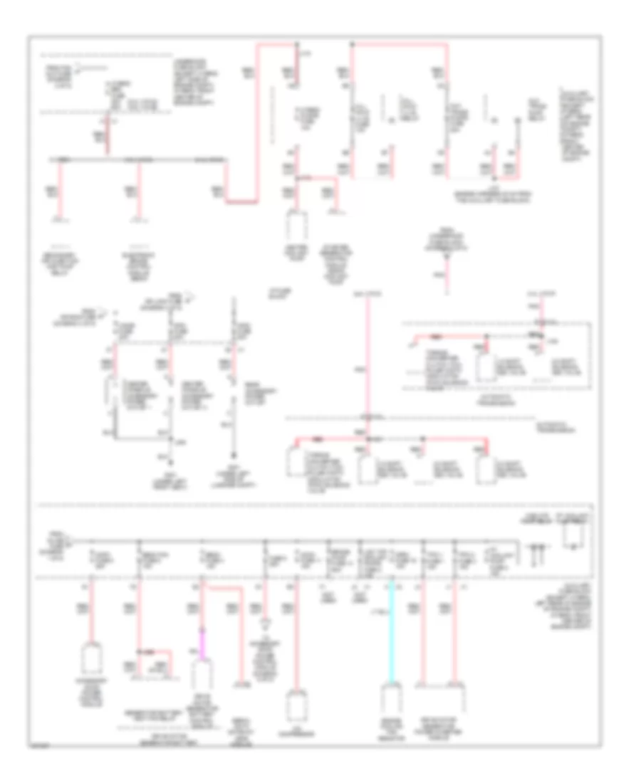
Power Distribution Wiring Diagram (4 of 5) for Saturn Vue Red Line 2009
List of elements for Power Distribution Wiring Diagram (4 of 5) for Saturn Vue Red Line 2009:
Power Distribution Wiring Diagram (5 of 5) for Saturn Vue Red Line 2009
List of elements for Power Distribution Wiring Diagram (5 of 5) for Saturn Vue Red Line 2009: