POWER DISTRIBUTION
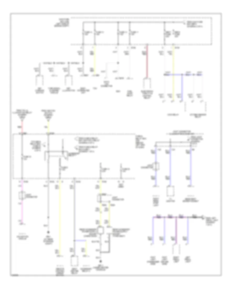
Power Distribution Wiring Diagram (1 of 4) for Subaru B9 Tribeca Limited 2006

List of elements for Power Distribution Wiring Diagram (1 of 4) for Subaru B9 Tribeca Limited 2006:
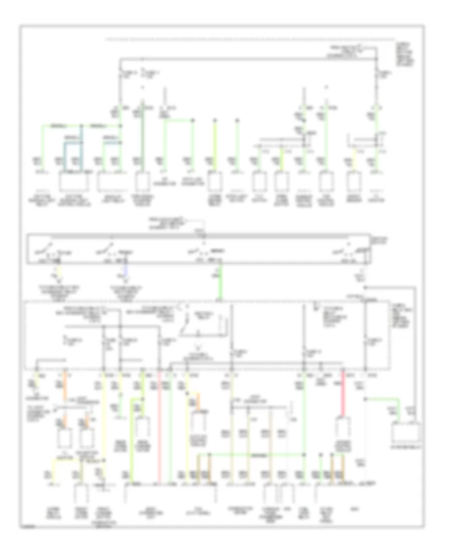
Power Distribution Wiring Diagram (2 of 4) for Subaru B9 Tribeca Limited 2006
List of elements for Power Distribution Wiring Diagram (2 of 4) for Subaru B9 Tribeca Limited 2006:
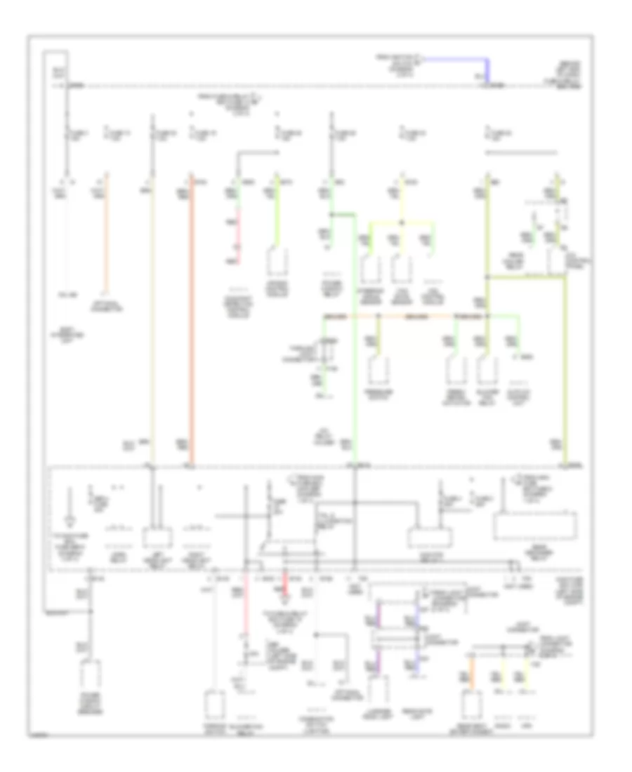
Power Distribution Wiring Diagram (3 of 4) for Subaru B9 Tribeca Limited 2006
List of elements for Power Distribution Wiring Diagram (3 of 4) for Subaru B9 Tribeca Limited 2006:
Power Distribution Wiring Diagram (4 of 4) for Subaru B9 Tribeca Limited 2006
List of elements for Power Distribution Wiring Diagram (4 of 4) for Subaru B9 Tribeca Limited 2006: