POWER DISTRIBUTION
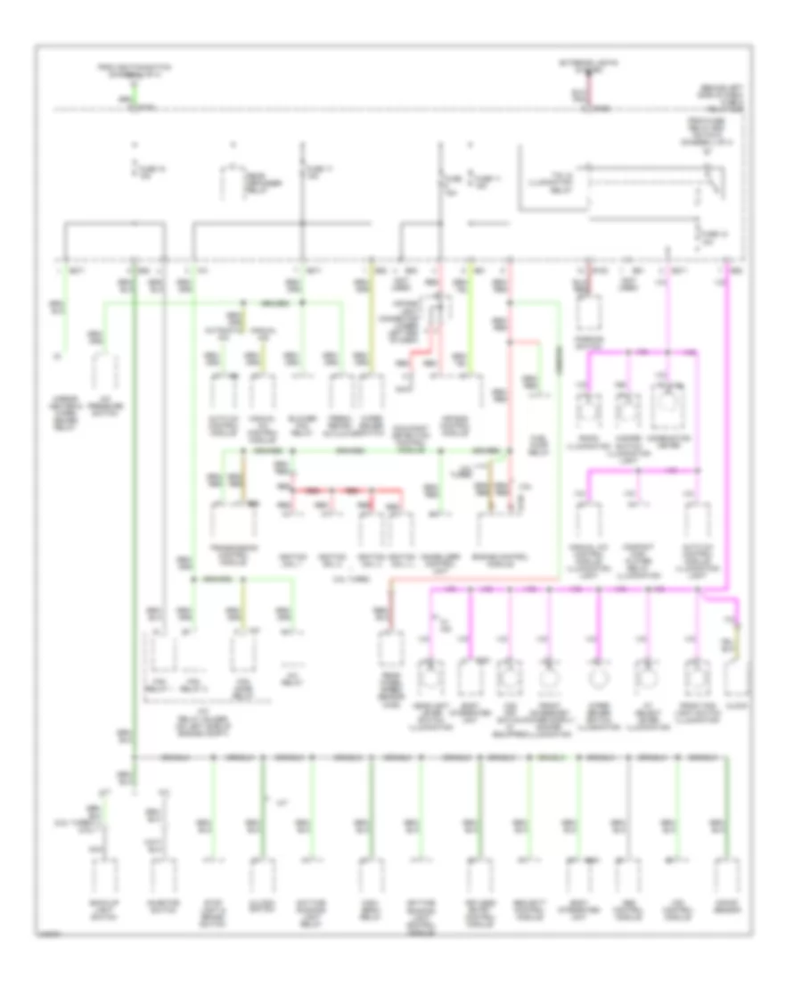
Power Distribution Wiring Diagram (1 of 4) for Subaru Forester X L.L. Bean Edition 2006

List of elements for Power Distribution Wiring Diagram (1 of 4) for Subaru Forester X L.L. Bean Edition 2006:
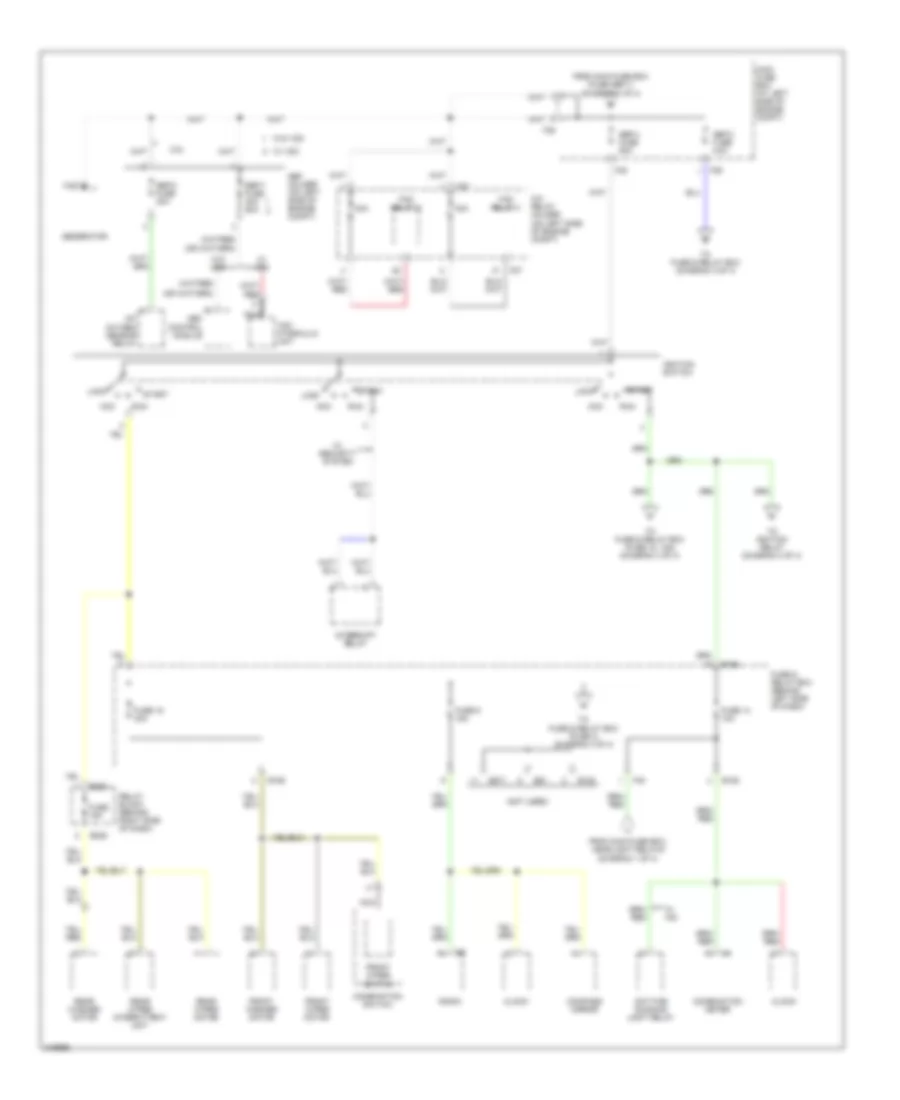
Power Distribution Wiring Diagram (2 of 4) for Subaru Forester X L.L. Bean Edition 2006
List of elements for Power Distribution Wiring Diagram (2 of 4) for Subaru Forester X L.L. Bean Edition 2006:
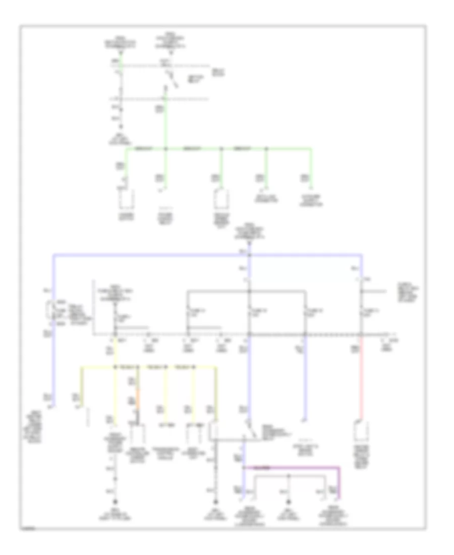
Power Distribution Wiring Diagram (3 of 4) for Subaru Forester X L.L. Bean Edition 2006
List of elements for Power Distribution Wiring Diagram (3 of 4) for Subaru Forester X L.L. Bean Edition 2006:
Power Distribution Wiring Diagram (4 of 4) for Subaru Forester X L.L. Bean Edition 2006
List of elements for Power Distribution Wiring Diagram (4 of 4) for Subaru Forester X L.L. Bean Edition 2006: