POWER DISTRIBUTION
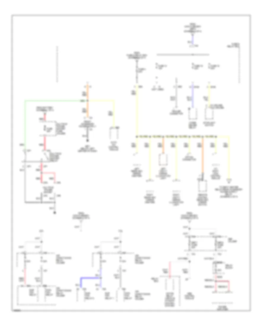
Power Distribution Wiring Diagram (1 of 4) for Subaru Legacy GT Limited 2002

List of elements for Power Distribution Wiring Diagram (1 of 4) for Subaru Legacy GT Limited 2002:
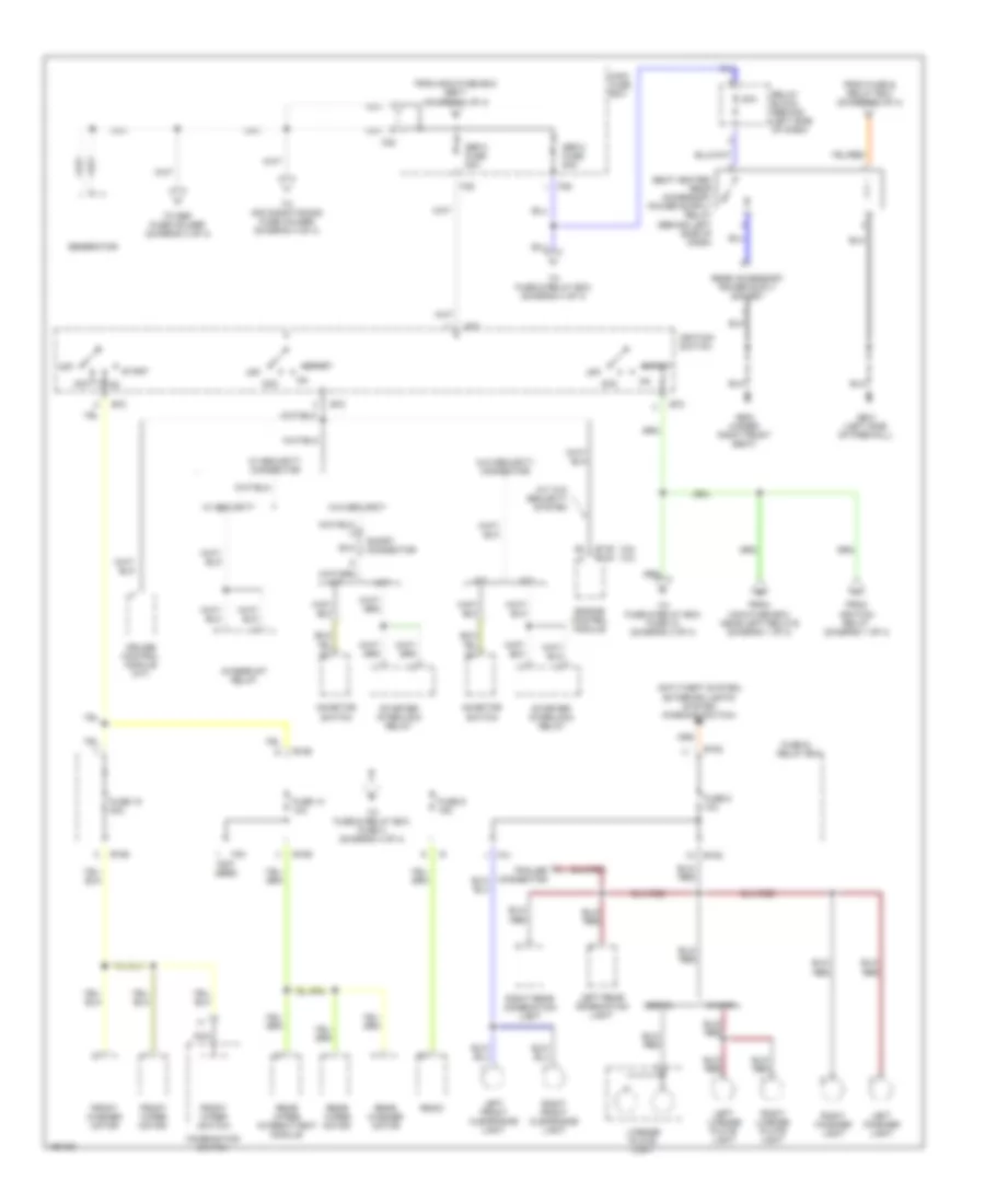
Power Distribution Wiring Diagram (2 of 4) for Subaru Legacy GT Limited 2002
List of elements for Power Distribution Wiring Diagram (2 of 4) for Subaru Legacy GT Limited 2002:
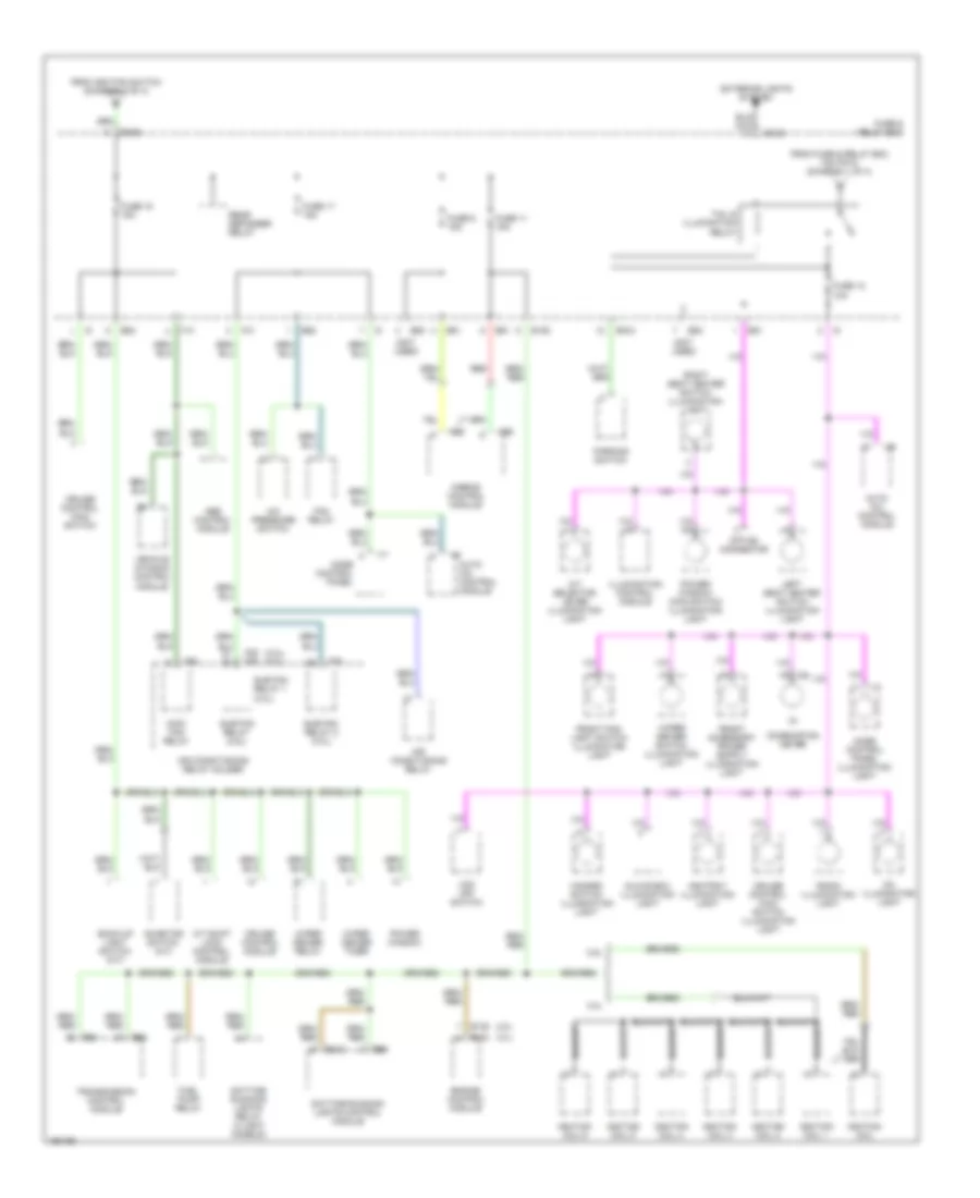
Power Distribution Wiring Diagram (3 of 4) for Subaru Legacy GT Limited 2002
List of elements for Power Distribution Wiring Diagram (3 of 4) for Subaru Legacy GT Limited 2002:
Power Distribution Wiring Diagram (4 of 4) for Subaru Legacy GT Limited 2002
List of elements for Power Distribution Wiring Diagram (4 of 4) for Subaru Legacy GT Limited 2002: