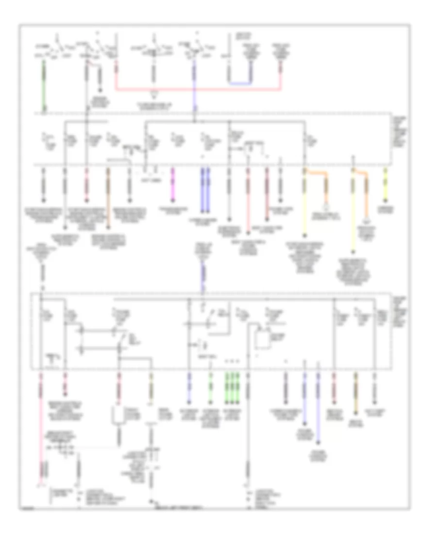
POWER DISTRIBUTION
Power Distribution Wiring Diagram (1 of 2) for Toyota 4Runner Limited 2004

List of elements for Power Distribution Wiring Diagram (1 of 2) for Toyota 4Runner Limited 2004:
- (behind left end of dash) junction connector 7
- A/f heater fuse 15a
- Abs mtr fuse 40a
- Abs sol fuse 50a
- Ac1
- Ac115v inv fuse 15a
- Ac115v inv relay
- Ac2
- Air conditioning system
- Air conditioning systems
- Air conditioning, engine controls, transmissions & cruise control systems
- Air sus fuse 50a
- Alt fuse 140a
- Alt-s fuse 7.5a
- Am1 fuse 50a
- Am2 fuse 30a
- Anti-lock brakes system
- Anti-theft, body computer, interior lights, power windows, door locks &
- Batt chg fuse 30a
- Battery
- Bo (on left "d" pillar)
- Body computer, door locks, anti-theft & power tops systems
- Computer data lines system
- Defog relay
- Dome fuse 10a
- Dr/lck fuse 20a
- Eb (on left front inner fender)
- Ecu-b fuse 10a
- Efi fuse 20a
- Electronic suspension system
- Engine controls system
- Engine controls, exterior lights, transmissions, cruise control, electronic suspension, shift interlock & anti-lock brakes systems
- Engine controls, transmissions & cruise control systems
- Engine controls, warning, garage door opener, instrument cluster & headlights systems
- Engine room r/b (on left side of engine compt)
- Etcs fuse 10a
- Exterior lights & headlights systems
- Exterior lights system
- Fr fog fuse 15a
- From short pin (diagram 1 of 2)
- Gnd
- Head relay
- Headlights system
- Heater fuse 60a
- Horn fuse 10a
- Horns & anti-theft systems
- Ig relay
- J/b fuse 50a
- J41
- Junction connector (behind right kick panel)
- Junction connector (on left front of engine compartment, near battery)
- Junction connector 1 (on left front of engine compartment, near battery)
- Junction connector 2 & 3 (on left front of engine compartment, near battery)
- Junction connector 20
- Junction connector 40 & 41 j40 (on left side of cargo area, near "d" pillar)
- Main switch
- Navigation & sound systems
- Obd fuse 7.5a
- Power outlet (115v)
- Power seats system
- Radio fuse 20a
- Red
- Seat heater fuse 25a
- Short pin
- Starting/ charging system
- Stop fuse 10a
- To ecu-b (diagram 1 of 2)
- To ig 1 fuse (diagram 2 of 2)
- To ignition switch (diagram 2 0f 2)
- To ignition switch (diagram 2 of 2)
- To tail relay (diagram 2 of 2)
- Towing brk fuse 30a
- Towing fuse 30a
- Towing fuse 40a
- Trn- haz fuse 15a
- Voltage inverter
Power Distribution Wiring Diagram (2 of 2) for Toyota 4Runner Limited 2004
List of elements for Power Distribution Wiring Diagram (2 of 2) for Toyota 4Runner Limited 2004:
- (behind right center of dash) center j/b
- (not used)
- 4wd fuse 20a
- A11
- Acc
- Acc fuse 7.5a
- Am1
- Am2
- Anti-theft system
- B11
- B12
- B13
- Bcm
- Bl (below left front seat)
- Body computer & power windows systems
- Body computer system
- Body ecu
- Cig fuse 10a
- Cigarette lighter
- D p/seat fuse 30a
- Dc skt relay
- Driver side j/b (behind lower left end of dash)
- E12
- E16
- E20
- E22
- E23
- Ecu-ig fuse 10a
- Electronic suspension system
- Engine controls system
- Engine controls, body computer, mirrors, air conditioning & sound systems
- Engine controls, cruise control & anti-lock brakes systems
- Engine controls, transmissions & cruise control systems
- Exterior lights system
- F13
- Fr wip-wsh fuse 30a
- From am1 fuse (diagram 1 of 2)
- From am2 fuse (diagram 1 of 2)
- From ig relay (diagram 1 of 2)
- From ignition switch (diagram 2 of 2)
- From j/b
- From main switch (diagram 1 of 2)
- Front power outlet
- Fuse 50 (diagram 1 of 2)
- Gauge fuse 7.5a
- Ig1
- Ig1 fuse 15a
- Ig2
- Ign fuse 10a
- Ignition switch
- Interior lights & instrument cluster systems
- J11
- J13
- J25
- J28
- J29
- J30
- J31
- J32
- J40
- J41
- Junction connector 24 (behind lower right center of dash)
- Junction connector 5 (behind right kick panel)
- K10
- L17
- L20
- Lock
- Mirrors system
- Near "d" pillar)
- Off on
- On off
- P p/seat fuse 30a
- Pnk
- Power fuse 30a
- Power outlet fuse 15a
- Power relay
- Power tops system
- Power windows system
- Rear power outlet
- Red
- Rr wash fuse 15a
- Seats & memory systems
- Seats system
- Secu/ horn fuse 10a
- Sig
- Srs fuse 10a
- St2
- Sta fuse 7.5a
- Start
- Starting/charging, engine controls & transmissions systems
- Starting/charging, engine controls, instrument cluster, interior lights & warning systems
- Starting/charging, exterior lights, defogger, air conditioning, door locks & anti-lock brakes systems
- Tail fuse 10a
- Tail relay
- To driver side j/b (diagram 2 of 2)
- Transmissions system
- Trly
- Wig
- Wiper/washer & power tops systems
- Wiper/washer system