POWER DISTRIBUTION
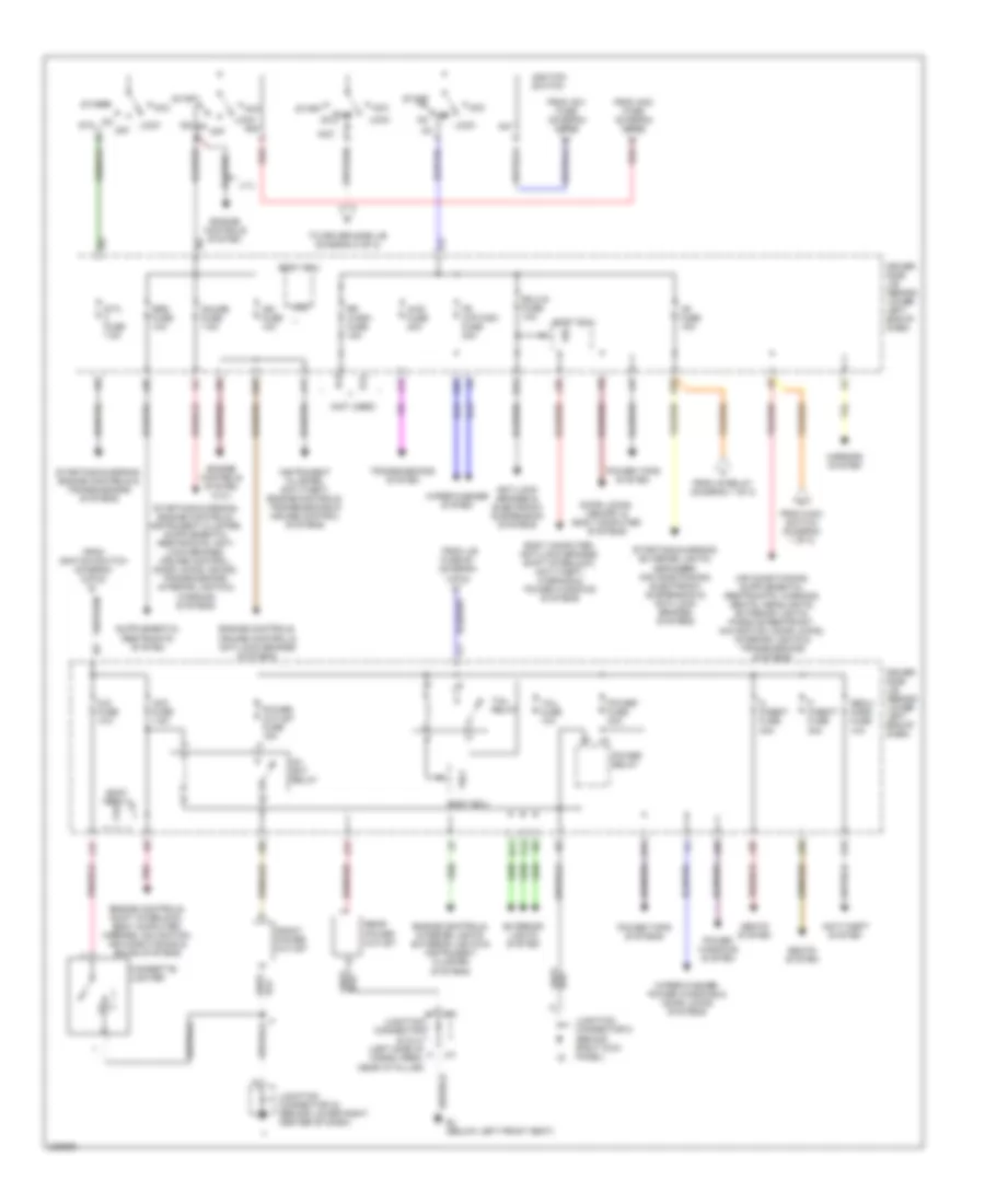
Power Distribution Wiring Diagram (1 of 2) for Toyota 4Runner SR5 2006

List of elements for Power Distribution Wiring Diagram (1 of 2) for Toyota 4Runner SR5 2006:
- (behind instrument cluster) junction connector 14 & 15
- (behind instrument cluster) junction connector 20
- (behind left end of dash) junction connector 7
- (on left side of cargo area) voltage inverter
- A/f heater fuse 15a
- A/pump fuse 50a (4.7l)
- Abs mtr fuse 40a
- Abs sol fuse 30a
- Ac1
- Ac115v inv fuse 15a
- Ac115v inv relay
- Ac2
- Air conditioning system
- Air conditioning systems
- Air conditioning, engine controls, mirrors, navigation & sound systems
- Air sus fuse 50a
- Alt fuse 140a
- Alt-s fuse 7.5a
- Am1 fuse 50a
- Am2 fuse 30a
- Anti-lock brakes system
- Batt chg fuse 30a
- Battery
- Bo (on left "d" pillar)
- Body computer, door locks, anti-theft & power windows systems
- Computer data lines system
- Cruise control, engine controls transmissions & sound systems
- Defog relay
- Dome fuse 10a
- Dr/lck fuse 20a
- Eb (on left front inner fender)
- Ecu-b fuse 10a
- Efi fuse 20a
- Electronic suspension system
- Engine controls system
- Engine controls, exterior lights, transmissions, cruise control, electronic suspension, shift interlock & anti-lock brakes systems
- Engine controls, transmissions & cruise control systems
- Engine room r/b (on left side of engine compt)
- Etcs fuse 10a
- Exterior lights & headlights systems
- Exterior lights system
- Fr fog fuse 15a
- From short pin (diagram 1 of 2)
- Gnd
- Head relay
- Headlights system
- Heater fuse 60a
- Horn fuse 10a
- Horns & anti-theft systems
- Ig relay
- Interior lights, engine controls, warning, navigation, garage door opener, sound, air conditioning, instrument cluster & headlights systems
- J/b fuse 50a
- J14
- J15
- J41
- Junction connector 1 (on left front of engine compt, near battery)
- Junction connector 3 (on left front of engine compt, near battery)
- Junction connector 40 & 41 j40 (on left side of cargo area, near "d" pillar)
- Junction connector 5 (behind right kick panel)
- Main switch
- Navigation & sound systems
- Obd fuse 7.5a
- Power outlet (115v)
- Radio fuse 20a
- Red
- Seat heater fuse 25a
- Seats system
- Short pin
- Starting/ charging system
- Stop fuse 10a
- To ecu-b (diagram 1 of 2)
- To ig 1 fuse (diagram 2 of 2)
- To ignition switch (diagram 2 of 2)
- To tail relay (diagram 2 of 2)
- Towing brk fuse 30a
- Towing fuse 30a
- Towing fuse 40a
- Trn- haz fuse 15a
Power Distribution Wiring Diagram (2 of 2) for Toyota 4Runner SR5 2006
List of elements for Power Distribution Wiring Diagram (2 of 2) for Toyota 4Runner SR5 2006:
- (not used)
- 4.7l
- 4wd fuse 20a
- A11
- Acc
- Acc fuse 7.5a
- Am1
- Am2
- Anti-lock brakes & electronic suspension systems
- Anti-theft system
- B11
- B12
- B13
- Bl (below left front seat)
- Body computer, anti-lock brakes, shift interlock, anti-theft, warning & power windows systems
- Body ecu
- Cig fuse 10a
- Cigarette lighter
- D p/seat fuse 30a
- Dc skt relay
- Door locks, memory & body computer systems
- Driver side j/b (behind lower left end of dash)
- E12
- E20
- E22
- E23
- Ecu-ig fuse 10a
- Engine controls system
- Engine controls system (4.0l)
- Engine controls, cruise control & anti-lock brakes systems
- Engine controls, interior lights, exterior lights & instrument cluster systems
- Engine controls, shift interlock, body computer, mirrors, navigation, air conditioning & sound systems
- Exterior lights system
- F13
- Fr wip-wsh fuse 30a
- From am1 fuse (diagram 1 of 2)
- From am2 fuse (diagram 1 of 2)
- From ig relay (diagram 1 of 2)
- From ignition switch (diagram 2 of 2)
- From j/b
- From main switch (diagram 1 of 2)
- Front power outlet
- Fuse 50 (diagram 1 of 2)
- Gauge fuse 7.5a
- Ig1
- Ig1 fuse 15a
- Ig2
- Ign fuse 10a
- Ignition switch
- Instrument cluster, anti-theft, engine controls, transmissions & cruise control systems
- J11
- J13
- J25
- J28
- J29
- J30
- J31
- J32
- J40
- J41
- Junction connector 24 (behind lower right center of dash)
- Junction connector 40 & 41 (left side of cargo area, near "d" pillar)
- Junction connector 5 (behind right kick panel)
- K10
- L17
- L20
- Lock
- Mirrors system
- Off on
- On off
- P p/seat fuse 30a
- Pnk
- Power fuse 30a
- Power outlet fuse 15a
- Power relay
- Power tops system
- Power tops systems
- Power windows system
- Rear power outlet
- Red
- Rr wash fuse 15a
- Seats system
- Secu/ horn fuse 10a
- Sig
- Srs fuse 10a
- St2
- Sta fuse 7.5a
- Start
- Starting/charging, engine controls & transmissions systems
- Starting/charging, exterior lights, defogger, air conditioning, electronic suspension & anti-lock brakes systems
- Tail fuse 10a
- Tail relay
- To driver side j/b (diagram 2 of 2)
- Transmissions system
- Trly
- Wig
- Wiper/washer system
- Wiper/washer, power windows & door locks systems