POWER DISTRIBUTION
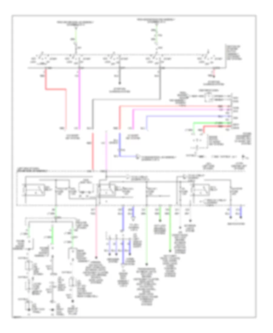
Power Distribution Wiring Diagram (1 of 4) for Toyota 4Runner Trail 2013

List of elements for Power Distribution Wiring Diagram (1 of 4) for Toyota 4Runner Trail 2013:
- (left side of engine compt) engine room r/b assembly
- A/c comp fuse 10a
- Abs 1 fuse 50a
- Abs 2 fuse 30a
- Air conditioning system
- Air pmp fuse 50a
- Air pmp htr fuse 10a
- Alt fuse 140a
- Alt-s fuse 7.5a
- Am2 fuse 7.5a
- Amp fuse 30a
- Anti-lock brakes system
- Anti-lock brakes, shift interlock, cruise control & exterior lights systems
- Anti-theft & door lock systems
- Battery
- Def fuse 30a
- Defogger system
- Deicer fuse 20a
- Dome fuse 10a
- Door locks & anti-theft systems
- Door locks, trunk, tailgate, fuel doors, interior lights, anti-theft & power windows systems
- Ecu-b fuse 10a
- Engine controls system
- Engine room j/b assembly (left side of engine compt)
- Etcs fuse 10a
- Exterior lights system
- Fa2
- H-lp hi fuse 20a
- H-lp hi relay
- H-lp lo relay
- Htr fuse 50a
- Inv fuse 80a (400w)
- Mayday fuse 7.5a
- Mir htr fuse 10a
- Navigation & sound systems
- Navigation system
- P/i-b fuse 80a
- Pnk
- Prb fuse 30a
- Ptc htr 1 fuse 50a
- Ptc htr 2 fuse 30a
- Ptc htr 3 fuse 30a
- Rad 1 fuse 10a
- Red
- Security fuse 10a
- Shift interlock system
- Short pin
- Smart fuse 7.5a
- Sound systems
- St fuse 30a
- Starting/ charging system
- Starting/charging system
- Stop fuse 10a
- Strg lock fuse 20a
- Sub batt fuse 30a
- To driver side j/b assembly (diagram 3 of 4)
- To engine room j/b assembly (diagram 3 of 4)
- To engine room r/b 3 assembly (diagram 4 of 4)
- To ignition or starter switch assembly (diagram 2 of 4)
- To j/b 5 (diagram 2 of 4)
- Towing brk fuse 30a
- Towing fuse 30a
- Towing tail fuse 30a
- Trunk, tailgate, fuel doors system
- Turn & haz fuse 15a
- W/ smart key system
- W/o smart key system
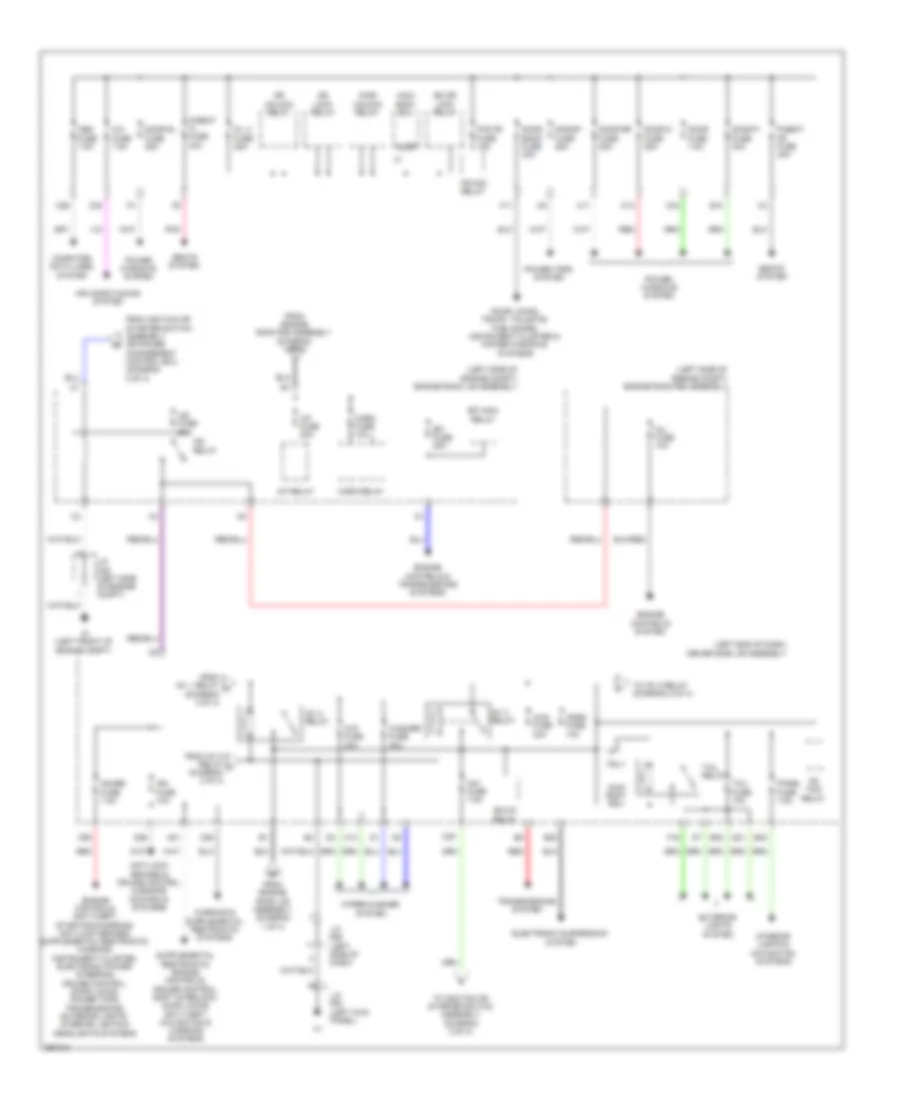
Power Distribution Wiring Diagram (2 of 4) for Toyota 4Runner Trail 2013
List of elements for Power Distribution Wiring Diagram (2 of 4) for Toyota 4Runner Trail 2013:
- (center of dash) j/b 5
- (left end of dash) driver side j/b assembly
- 3 of 4)
- A19
- Acc
- Acc fuse 7.5a
- Acc relay
- Accd
- Air conditioning, anti-lock brakes, exterior lights & starting/ charging systems
- Am1
- Am2
- Am21
- Am22
- Anti-lock brakes & defogger systems
- Anti-theft, trunk, tailgate, fuel doors, door locks, wiper/ washer & power windows systems
- B17
- B35
- B39
- B69
- C14
- C31
- C33
- C48
- C52
- D11
- D27
- D31
- Defogger system
- Ecu-ig 1 fuse 10a
- Ecu-ig 2 fuse 10a
- Engine switch (w/ smart key system)
- Exterior lights system
- F30
- F55
- F56
- F56 j/c f55 & f56 (left side of dash) f55
- F57
- F58
- F80
- F81
- Fa2
- Fn1
- From driver side j/b assembly (diagram 3 of 4)
- From engine room r/b assembly (diagram 1 of 4)
- From ig1 3 relay (diagram j
- Ig1
- Ig1 1 relay
- Ig1 5 relay
- Ig1 fuse 7.5a
- Ig1d
- Ig2
- Ig2d
- Ignition or starter switch assembly (w/o smart key system)
- J/b 4 (left side of dash)
- J/c a37 (left side of engine compt)
- J/c f55 & f56 (left side of dash)
- J/c f56 (left side of dash)
- J/c f57 & f58 (right end of dash)
- J/c f63 (left kick panel)
- J/c f64 (center left of dash)
- J/c f65 (right kick panel)
- J/c n22 (w/ 120v power outlet) (above right rear wheelwell)
- Lock
- Main body ecu
- Mirrors, navigation, shift interlock, exterior lights, instrument cluster, anti-lock brakes, sound & door locks systems
- N2 (base of right "d" pillar)
- Off
- P/outlet fuse 15a
- Pnk
- Power management control ecu (w/ smart key system)
- Power point socket assembly
- Power point socket assembly 2
- Rear power point socket assembly
- Red
- S/htr fr fuse 20a
- Seats system
- Ssw1
- Ssw2
- St1
- St2
- Start
- Starting/ charging system
- To engine room j/b assembly (diagram 3 of 4)
- To engine room r/b 3 assembly (diagram 4 of 4)
- To ig1 2 relay (diagram 3 of 4)
- To j/b 4 (diagram 4 of 4)
- Transmissions, exterior lights, anti-lock brakes, instrument cluster, headlights, shift interlock, navigation, cruise control, sound, door locks, electronic power steering & warning systems
- W/ smart key system
- W/o smart key system
- Wiper/ washer system
Power Distribution Wiring Diagram (3 of 4) for Toyota 4Runner Trail 2013
List of elements for Power Distribution Wiring Diagram (3 of 4) for Toyota 4Runner Trail 2013:
- (left end of dash) driver side j/b assembly
- (left side of engine compt) engine room j/b assembly
- (left side of engine compt) engine room r/b assembly
- 4wd fuse 20a
- A/c fuse 7.5a
- A/f fuse 20a
- A/f relay
- A1 (left front of engine compt)
- Air conditioning system
- Altb
- Am1 fuse 7.5a
- Anti-lock brakes & cruise control & engine controls systems
- B10
- B20
- B32
- B40
- Bk dr lock relay
- Bk/up relay
- C11
- C12
- C13
- C26
- C29
- C34
- C35
- C38
- C51
- C55
- Computer data lines system
- D-dr unlock relay
- D/l 2 fuse 25a
- D21
- D26
- Door back fuse 30a
- Door d fuse 25a
- Door fuse 7.5a
- Door locks, trunk, tailgate, fuel doors, instrument cluster & power windows systems
- Door p fuse 30a
- Door rl fuse 25a
- Door rr fuse 25a
- Dr lock relay
- Dr unlock relay
- Efi fuse 25a
- Efi main relay
- Electronic suspension system
- Engine controls & transmissions systems
- Engine controls system
- Exterior lights system
- F11
- F16
- Fog fr fuse 15a
- Fr fog relay
- From engine room j/b assembly (diagram 1 of 4)
- From engine room r/b assembly (diagram 1 of 4)
- From ig1 1 relay h (diagram 2 of 4)
- From ig1 5 relay k (diagram 2 of 4)
- From ignition or starter switch assembly or power management control ecu (diagram 2 of 4)
- Gauge fuse 7.5a
- Horn fuse 10a
- Horn relay
- Ig1 2 relay
- Ig1 3 relay
- Ig2 fuse 20a
- Ig2 relay
- Ign fuse 10a
- Inj fuse 10a
- Interior lights & navigation systems
- J/c a38 (left side of engine compt)
- J/c f55 (left side of dash)
- J/c f63 (left kick panel)
- Kdss fuse 10a
- Main body ecu
- Obd fuse 7.5a
- P/seat fl fuse 30a
- P/seat fr fuse 30a
- Panel fuse 7.5a
- Pnk
- Power tops system
- Power windows system
- Red
- S/roof fuse 25a
- Seats system
- Tail fuse 10a
- Tail relay
- To ig1 5 relay (diagram 2 of 4)
- To ignition or starter switch assembly (diagram 2 of 4)
- Transmissions system
- Trly
- Washer fuse 20a
- Wip fuse 30a
- Wiper/washer system
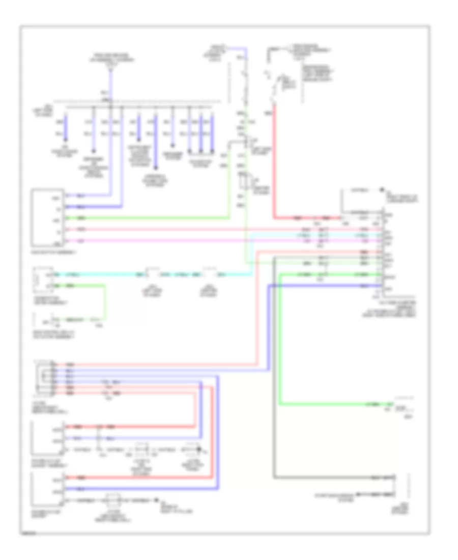
Power Distribution Wiring Diagram (4 of 4) for Toyota 4Runner Trail 2013
List of elements for Power Distribution Wiring Diagram (4 of 4) for Toyota 4Runner Trail 2013:
- (diagram 1 of 4)
- A13
- A38
- A66
- A67
- A79
- A91
- Ac1
- Ac2
- Acc1
- Acc2
- Acc3
- Acc4
- Air conditioning system
- B14
- B17
- B20
- B21
- B25
- B31
- B37
- B41
- B43
- B44
- B53
- B54
- B55
- C16
- C19
- Combination meter assembly
- Defogger system
- Defogger, air conditioning & seats systems
- Ecm
- Els2
- Engine room r/b 3 assembly (left side of engine compt)
- Excd
- F51
- F57
- F58
- Fa2
- Fn1
- From driver side j/b assembly (diagram 2 of 4)
- From engine room r/b assembly a
- From j/c a37 l (diagram 2 of 4)
- Fm1
- Gnd
- Ind
- Ind+
- Ind-
- Instrument cluster, sound & navigation systems
- Inv relay (400w)
- J/b (center of dash)
- J/b (left side of dash)
- J/b 4 (left side of dash)
- J/b 5 (center of dash)
- J/c f57 & f58 (right end of dash)
- J/c f65 (right kick panel)
- J/c n22 (above right rear wheelwell)
- Main switch assembly
- Mirrors & power tops systems
- N19
- N2 (base of right "d" pillar)
- N20
- N3 (right front of luggage compt)
- Navigation system
- Nr1
- Nsw
- Pnk
- Power outlet socket
- Power outlet socket assembly
- Ra1
- Red
- Rly
- Skid control ecu w/ actuator assembly
- Sp1
- Spd
- Starting/charging system
- Voltage inverter assembly (w/ power outlet (120v)) (right side of cargo area)